Switching power supply device

a power supply device and power supply technology, applied in the direction of ignition automatic control, process and machine control, instruments, etc., can solve the problems of increasing the number of components, increasing the size of the switching power supply, increasing the packaging surface area, etc., to eliminate the switching loss and minimize the switching loss

Inactive Publication Date: 2008-07-29
SANKEN ELECTRIC CO LTD
View PDF36 Cites 9 Cited by
  • Summary
  • Abstract
  • Description
  • Claims
  • Application Information

AI Technical Summary

Benefits of technology

[0005]In the meanwhile, research and development work has been progressively undertaken in recent days to provide a switching power supply wherein a reactor is connected to a primary winding of a transformer in series to allow a switch to execute switching operations through the use of energy stored in the reactor for thereby minimizing switching losses. In such a structure, in order to further eliminate the switching losses, the reactor needs to have a well-suited inductance value.
[0006]However, since the magnetic leakage transformer 111 merely has a fixed leakage inductance, the inductance of the reactor have been appropriately adjusted by connecting an external reactor to the primary winding 119 in series. This results in an increase in the number of component parts, an increase in costs, an increase in a packaging surface area and an increase in size of the switching power supply.
[0007]It is, therefore, an object of the present invention to provide a switching power supply wherein a transformer has a well-suited leakage inductance value with no external reactor while making it possible to achieve zero-voltage switching for thereby providing high efficiency and a minimized structure at low noises.

Problems solved by technology

This results in an increase in the number of component parts, an increase in costs, an increase in a packaging surface area and an increase in size of the switching power supply.

Method used


Image

  • Switching power supply device
  • Switching power supply device
  • Switching power supply device

Examples


embodiment 1

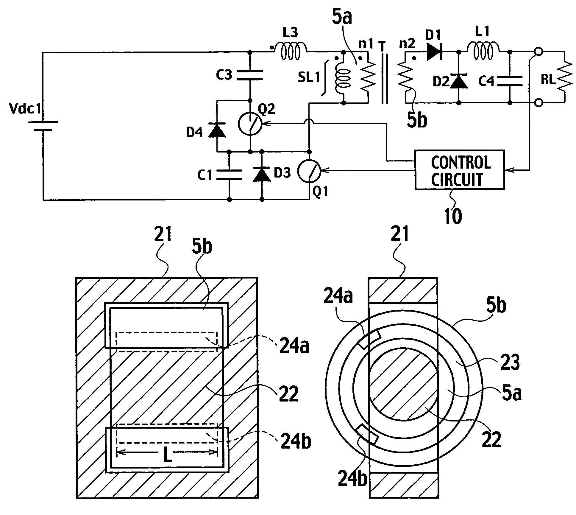
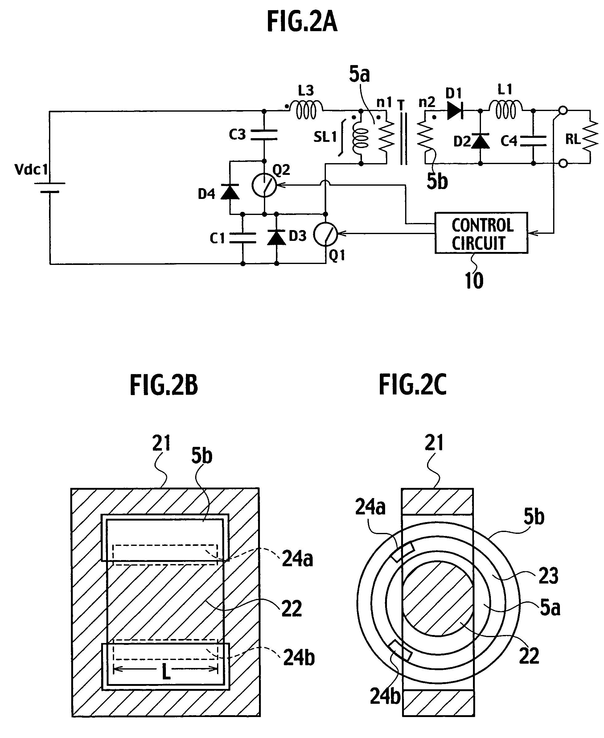
[0024]A switching power supply of a first embodiment features that when a main switch is turned on, electric power is directly supplied to a load via a secondary winding of a transformer while when the main switch is turned off, excitation energy stored in a primary winding of the transformer is stored in a capacitor C3 to turn on an auxiliary switch whereby first and third quadrants on a B-H curve of a core of the transformer is used and making up shortfalls in the excitation energy with energy from a reactor L3 allows a starting point on the B-H curve to rest on a lower end of the third quadrant whereas a saturable reactor is connected to the primary winding of the transformer in parallel whereby the saturable reactor is saturated at a terminating point of an on-period of the auxiliary switch to increase a current to cause a reverse voltage to sharply occur when the auxiliary switch is turned off for thereby permitting the main switch to achieve zero-voltage switching.

[0025]FIGS. ...

example 1

(Concrete Example 1 of Transformer T)

[0052]FIG. 7 is a structural view showing a concrete example 1 of an inner bobbin of the transformer. FIG. 8 is a structural view showing a concrete example 1 of an outer bobbin of the transformer. The transformer of the concrete example 1 is comprised of the main core 21 shown in FIG. 2B, a cylindrical inner bobbin 31 (shown in FIG. 7) on which the primary winding 5a is wound, and an outer bobbin 33 (shown in FIG. 8), formed with slits 34a, 34b each with a given length L along a circumferential direction of the primary winding 5a to which auxiliary cores 35a, 35b are inserted, which is larger in diameter than the first bobbin 31 and on which the secondary winding 5b is wound. The inner bobbin 31 and the outer bobbin 33 are made of resin material.

[0053]By adjusting the number of auxiliary cores and the length L, a well-suited leakage inductance value is obtained. Further, for the purpose of precluding the winding from dropping-off, the inner bobb...

example 2

Concrete Example 2 of Transformer

[0057]FIG. 9 is a structural view showing a concrete example 2 of an inner bobbin of the transformer. FIG. 10 is a structural view showing a concrete example 2 of an outer bobbin of the transformer. The transformer of the concrete example 2 is comprised of the main core 21 shown in FIG. 2B, the cylindrical inner bobbin 31 (shown in FIG. 9) on which the primary winding 5a is wound, and an outer bobbin 37 (shown in FIG. 10), larger in diameter than the first bobbin 31 and wound with the secondary winding 5b, which is made of insulating magnetic material such as plastic magnet material. The magnetic material may include ferrite and Permalloy.

[0058]By adjusting a magnetic permeability of insulation magnetic material, a well-suited leakage inductance value is obtained. Further, for the purpose of precluding the winding from dropping-off, the inner bobbin 31 has both ends formed with the stepped portions 31a and, likewise, the outer bobbin 37 has both ends...


PUM

PropertyMeasurementUnit
voltageaaaaaaaaaa
leakage inductanceaaaaaaaaaa
lengthaaaaaaaaaa

Abstract

A switching power supply includes: a first series circuit, connected to both terminals of a direct current power supply Vdc1, in which a primary winding 5a of a transformer T, a reactor L3 and a first switch Q1 are connected in series; a second series circuit, connected to both terminals of the primary winding 5a and the reactor L3, which includes a switch Q2 and a capacitor C3; a smoothing circuit D1, D2, L1, C4; and a control circuit 10 alternately turning on and turning off the switches Q1, Q2. The transformer T includes: a main core 21, formed with a magnetic circuit, on which the primary and secondary windings 5a, 5b are wound with a given gap 23; and a plurality of auxiliary cores 24a, 24b disposed in the given gap 23 with a given distance in a circumferential direction of the primary winding 5a. Further, the reactor L3 is formed of a leakage inductance of the transformer T.

Description

TECHNICAL FIELD[0001]The present invention relates to a switching power supply with high efficiency, small size, and low noises.BACKGROUND ART[0002]A switching power supply turns on or turns off a switch to control a current flowing through a primary winding of a transformer, and rectifies and smoothes a voltage developed across a secondary winding of the transformer, to supply the resulting current output to a load. Since the transformer used in such a switching power supply serves to transfer energy, a structure and a characteristic of the transformer play important roles.[0003]FIG. 1 is a view showing a structure of one example of a magnetic leakage transformer disclosed in Japanese Patent Application Laid-open No. 2000-340441. The magnetic leakage transformer 111 shown in FIG. 1 is comprised of an E-core 113, formed with a magnetic circuit, which is made of magnetic material, an I-core 115 that forms a main iron core together with the E-core 113, a primary winding 119 and a seco...

Claims


Application Information

Patent Timeline
Patent Type & Authority Patents(United States)
IPC IPC(8): H02M3/335H01F27/30H01F37/00H01F38/08
CPCH01F27/306H02M3/33569H01F38/08H01F37/00H02M2001/0064H02M1/0064H02M3/01
Inventor TSURUYA, MAMORU
Owner SANKEN ELECTRIC CO LTD
Why Eureka
Try Eureka