Control of reverse-conducting IGBT

Active Publication Date: 2016-06-30
ABB (SCHWEIZ) AG
View PDF2 Cites 6 Cited by
  • Summary
  • Abstract
  • Description
  • Claims
  • Application Information

AI Technical Summary

Benefits of technology

[0010]Further a control logic implementing the overlapping of the turn-on signals is provided. The control logic takes into account the safe operation of the invention such that the overlapping signals are prevented in some c

Problems solved by technology

However, as the power density increases, the operating temperature of the device ris

Method used


Image

  • Control of reverse-conducting IGBT
  • Control of reverse-conducting IGBT
  • Control of reverse-conducting IGBT

Examples


Embodiment Construction

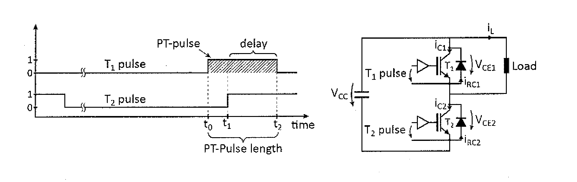
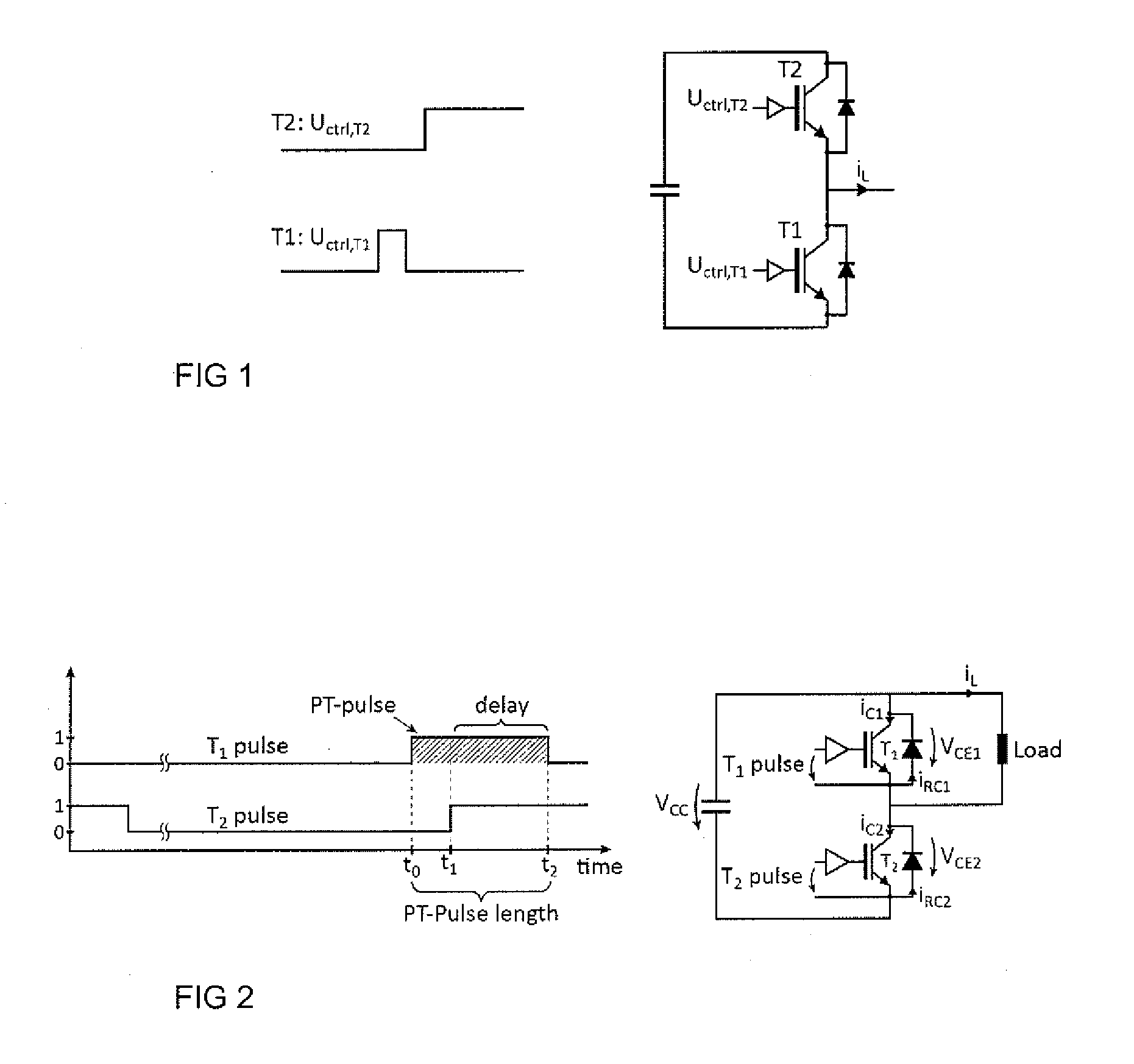
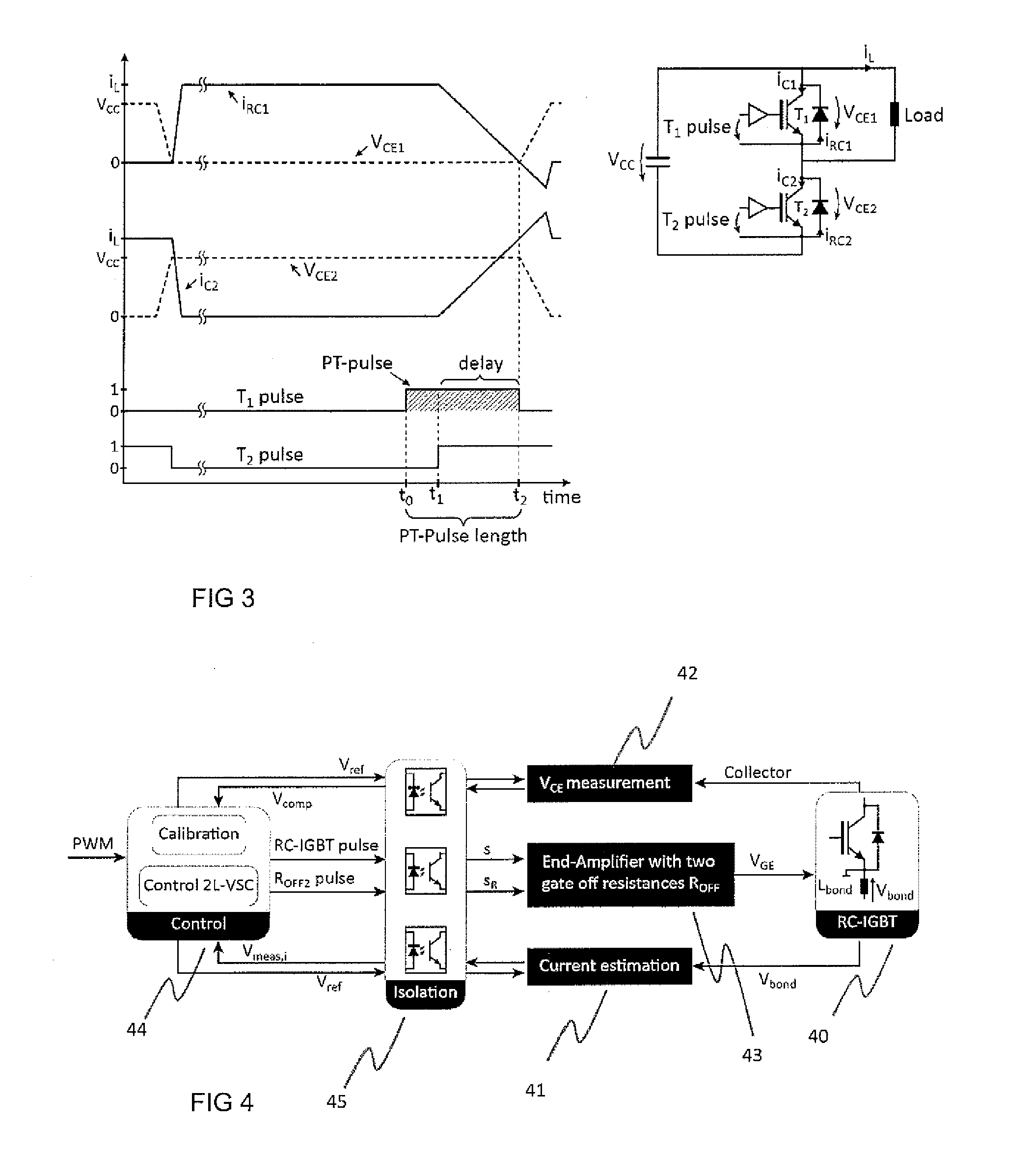
[0026]FIG. 2 shows the basic form and timing of the signals produced in the method of the present invention. In the method of the invention, a reverse-conducting IGBT (RC-IGBT) component is controlled when current flows through the component in the reverse conducting direction and when another switch component in series with the RC-IGBT is to be controlled to conducting state.

[0027]An RC-IGBT comprises a gate electrode to which control voltages are applied with respect to emitter potential of the RC-IGBT. In the invention, an RC-IGBT is in series connection with another controllable switch component. The other controllable switch component may be another RC-IGBT or another type of controllable component. RC-IGBTs allow the control of excess carrier distribution in reverse conduction mode and thus the switching losses at diode mode turn-off can be adjusted. To control the excess carrier distribution, extra trigger pulses called “Pre-trigger pulses (PT-Pulse)” are applied to the gate ...


PUM


Abstract

A method and an arrangement of controlling a reverse-conducting IGBT (RC-IGBT) component in a circuit comprising a series connection of controllable switch components where at least one of the controllable switch components is an RC-IGBT and the other component is to be controlled to a conductive state. The method comprising applying a pre-trigger pulse to the gate electrode of the RC-IGBT during reverse conduction of the RC-IGBT at a first time instant (t1), the pre-trigger pulse corresponding to a turn-on gate pulse, applying a turn-on gate pulse at a second time instant (t2) to the other controllable switch component of the series connection for controlling the other controllable switch component to a conductive state such that the pre-trigger pulse and the turn-on gate pulse overlap, and ending the pre-trigger pulse after a delay time at the third time instant (t3), the delay time being the time period when the turn-on gate pulse and the pre-trigger pulse overlap.

Description

FIELD OF THE INVENTION[0001]The invention relates to reverse-conducting insulated bi-polar transistors (RC-IGBT), and particularly to control of RC-IGBT.BACKGROUND OF THE INVENTION[0002]The increasing demand for large power ratings and power density of power converters has been a key motivation for the research and development of new power semiconductors technologies. Power semiconductors have for decades been a topic of intensive research and continual improvement, and are used in applications such as hybrid vehicles, renewable energies, and industrial. Improving semiconductor efficiency and increasing power density are the main development topics. However, as the power density increases, the operating temperature of the device rises and causes thermal cycling issues and shortens the lifetime of the semiconductor.[0003]To mitigate these problems, components called “reverse conducting” IGBTs (RC-IGBTs) have been developed. These semiconductors provide high power density and advantag...

Claims


Application Information

Patent Timeline
IPC IPC(8): H03K17/284H03K17/74H03K17/567
CPCH03K17/284H03K17/74H03K17/567H03K17/60H03K17/0414H03K17/08128H03K17/28
Inventor LIZAMA, IGNACIOBERNET, STEFFENLAITEINEN, MATTI
Owner ABB (SCHWEIZ) AG
Why Eureka
Try Eureka