Portable electronic spirometer

a spirometer and electronic technology, applied in the field of portable spirometers, can solve the problems of preventing a highly accurate or complete determination of flow properties, low level of accuracy of spirometers, and no electronic recording and transmission means of spirometers, etc., to achieve the effect of increasing the measured air pressur

Inactive Publication Date: 2006-06-20
DYNAMIC MT
View PDF20 Cites 66 Cited by
  • Summary
  • Abstract
  • Description
  • Claims
  • Application Information

AI Technical Summary

Benefits of technology

[0012]According to the invention there is provided a spirometer having a housing with an elongated flow chamber open at one end, a pressure sensing end opposite the open end and an outlet passageway intercepting the flow chamber at an angle • and proximate the pressure sensing end. A differential pressure sensor is coupled to the pressure sensing end from a port at an angle • to an axis of the flow chamber. The angle • is substantially greater than 0° but substantially less than 180° while the angle • may take any value between 90° and 180°, such that a significantly increased measured air pressure results over that measured when α=180° and •=90°.

Problems solved by technology

While these spirometers are inexpensive and, therefore widely used, they suffer from certain disadvantages.
Typically, these spirometers have a low level of accuracy due to friction and other artefacts of their mechanical construction.
Other limitations arise because the inertia of the mechanical vane or wheel prevents a reliable flow measurement as a function of time, and so the spirometers are only capable of measuring an approximation of the peak flow.
In addition, ordinarily such spirometers have no means of recording and transmitting the results in electronic form.
However, the underlying mechanical means of flow measurement prevents a highly accurate or complete determination of the flow properties.
If a user does not use a correct breathing technique, coughs, or does not exhale forcefully enough, the peak flow meter will have an inaccurate result.
Because of the limitations described above, existing mechanical monitoring spirometers are not able to make this determination.
The restriction or screen may trap contaminants from the user's breath which could alter the flow properties of the spirometer.
These contaminants may also spread disease from one user to another and the spirometer must be carefully sterilized.
For these reasons many pneumotachographs provide filters or membranes to protect the sensors, but these add to the complexity of the spirometer and reduce its sensitivity to air flow.
The pressure transducers, which are used to sense the pressure on either side of the restriction, are often of an expensive design making them too costly to be used widely as monitoring spirometers.
This limitation results because the processors and memory used in these electronic spirometers have a limited processing speed and size, and are unable to make accurate determination of flow versus time in real time.
A hardwired ROM memory on such pneumotachographs is an additional drawback because it requires physical replacement of the memory spirometer to accommodate an improved or customized data acquisition algorithm.
The data are also stored in RAM memory and, as a result, are lost when power is interrupted.
Due to the low sensitivity of the spirometer, heavy analog filtering is required.
Such filtering lowers the time response of the spirometer, and results in less accurate data being recorded.
A peak flow result obtained with the wrong technique is useless, and so the technique used must be monitored.
If the spirometer is to be used by a patient at home this type of manual correction is not convenient or practical.

Method used


Image

  • Portable electronic spirometer
  • Portable electronic spirometer
  • Portable electronic spirometer

Examples


Embodiment Construction

Spirometer Construction

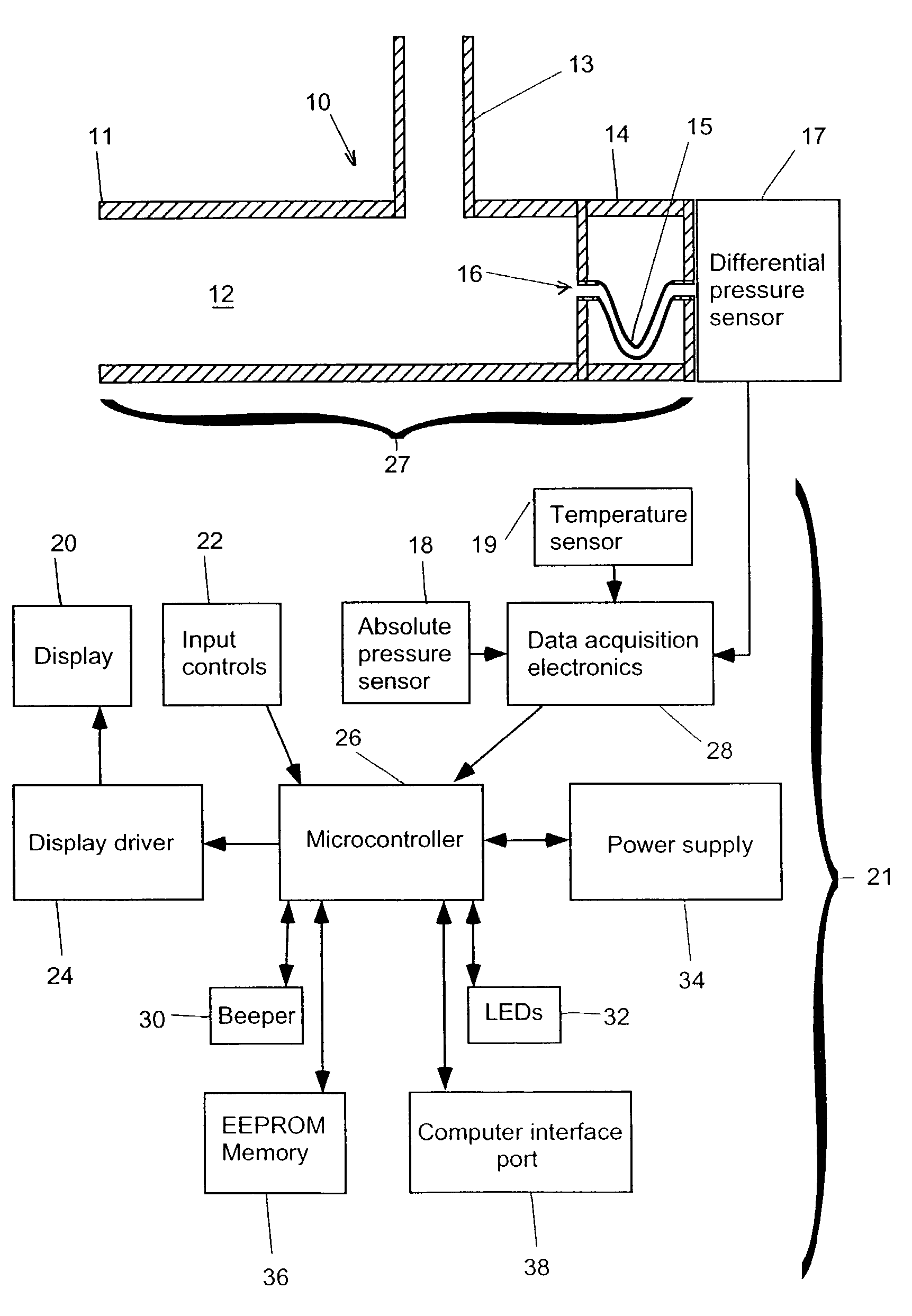
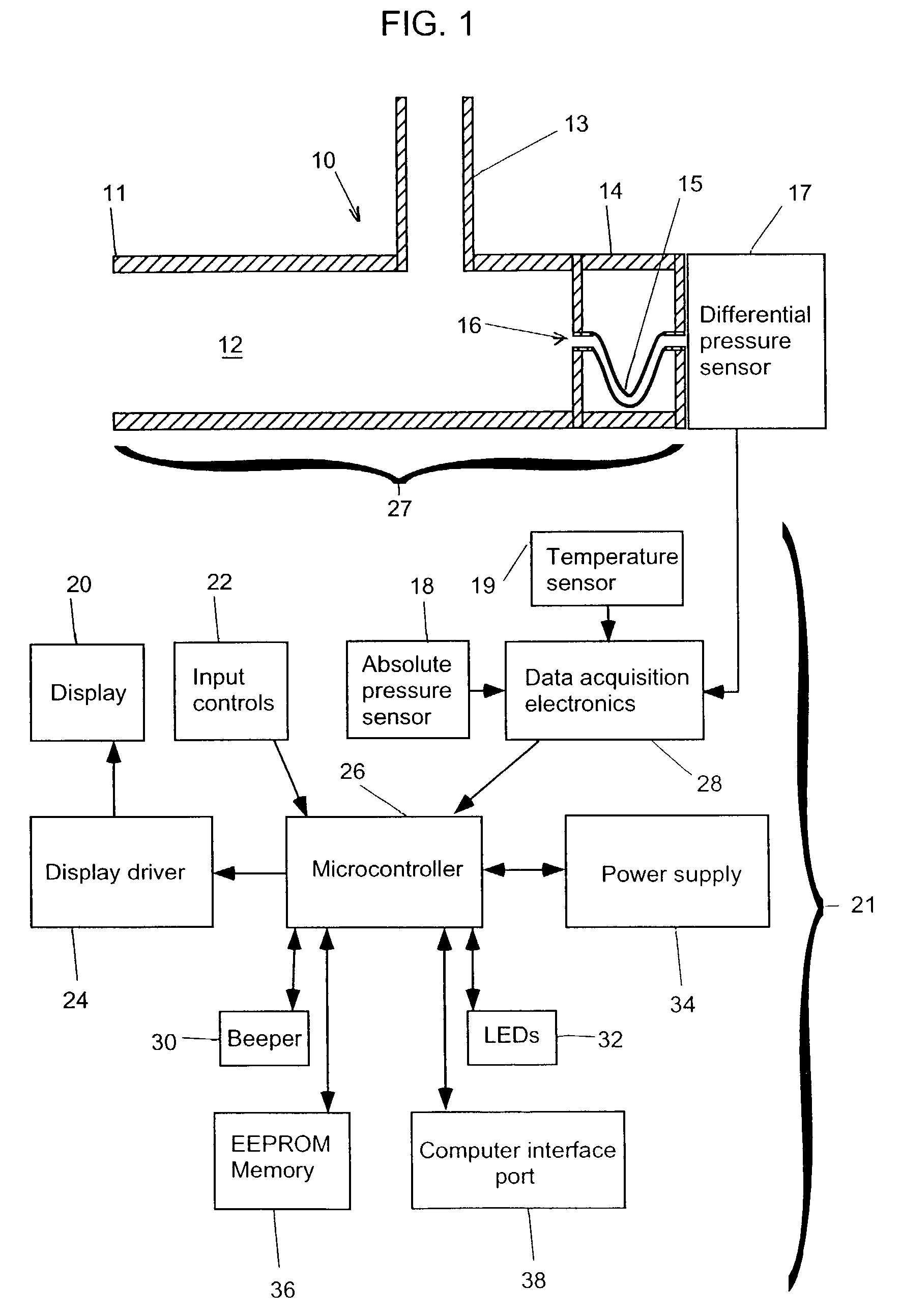
[0030]Referring to FIG. 1, the spirometer 10 consists of a housing 27 having a flow chamber 12, with a mouthpiece 11 and a meander passageway structure 61. The meander passageway structure 61 consists of a housing compartment 14 having end walls 63 and 65 at opposite ends and a hollow meander tube 15 whose meander passageway 16 is bent and opens through end walls 63 and 65 to provide fluid communication between the flow chamber 12 and a differential pressure sensor 17. The meander tube 15 could be replaced by, for example, a block of material with a bore therethrough. A differential pressure sensor 17 is located at an end of the flow chamber 12 opposite the mouthpiece 11. The meander tube 15 is used to protect the pressure sensor 17 from the direct flow of air so that contaminants from a user's breath will not enter the pressure sensor 17. An outlet tube 13 intersects the flow chamber 12 transversely. The meander tube 15 and crosshatched area may be constructe...


PUM


Abstract

A spirometer having a housing with an elongated flow chamber open at one end, a pressure sensing end opposite the open end and an outlet passageway intercepting the flow chamber at an angle α and proximate the pressure sensing end. A differential pressure sensor is coupled to the pressure sensing end from a port at an angle β to an axis of the flow chamber. The angle α is substantially greater than 0° but substantially less than 180° while the angle β may range from 90° to 180°, such that a significantly increased measured air pressure results over that measured when α=180° and β=90°.

Description

FIELD[0001]The present invention relates to a portable spirometer for monitoring lung function and for transferring spirometer data to other computers.BACKGROUND OF THE INVENTION[0002]A spirometer is a device that monitors respiration. A spirometer can be used for the diagnosis and monitoring of pulmonary diseases, particularly asthma and COPD (smoker's cough). Spirometers are also used to monitor the performance of athletes, as well as screen for occupational health problems such as black lung disease or silicosis. Spirometers are generally divided into two classes which have different specifications and purposes. The first class of spirometer are diagnostic spirometers which are used by physicians for the diagnosis of a person's respiratory condition. Diagnostic spirometers must be able to measure many different parameters of respiratory flow and must have a high degree of accuracy. The second class of spirometers are monitoring spirometers which are used to monitor the condition ...

Claims


Application Information

Patent Timeline
Patent Type & Authority Patents(United States)
IPC IPC(8): A61B5/00A61B5/087
CPCA61B5/0871A61B2560/0242
Inventor BRAWNER, DAVIDHEGARTY, CHRISTOPHER
Owner DYNAMIC MT
Why Eureka
Try Eureka