Vehicle lamp

a vehicle lamp and light source technology, applied in the field of vehicle lamps, can solve the problems of increasing the cost of the vehicle lamp corresponding to the additional light emitting element, and achieve the effect of low cost and selectively performing high beam irradiation

Inactive Publication Date: 2016-04-07
KOITO MFG CO LTD
View PDF10 Cites 6 Cited by
  • Summary
  • Abstract
  • Description
  • Claims
  • Application Information

AI Technical Summary

Benefits of technology

[0008]The invention of this application provides a vehicle lamp that is configured to selectively perform low beam irradiation and high beam irradiation by reflecting a light beam from a light emitting element forward using a reflector, and is capable of forming required light distribution patterns at a low cost.

Problems solved by technology

In the vehicle lamp described in Japanese Patent No. 4335621, the horizontal cut-off line and the oblique cut-off line are formed by turning on separate light emitting elements at the time of the low beam irradiation, and another light emitting element is additionally turned on at the time of the high beam irradiation, and hence the cost of the vehicle lamp may be increased correspondingly to the additional light emitting element.

Method used


Image

  • Vehicle lamp
  • Vehicle lamp
  • Vehicle lamp

Examples


Embodiment Construction

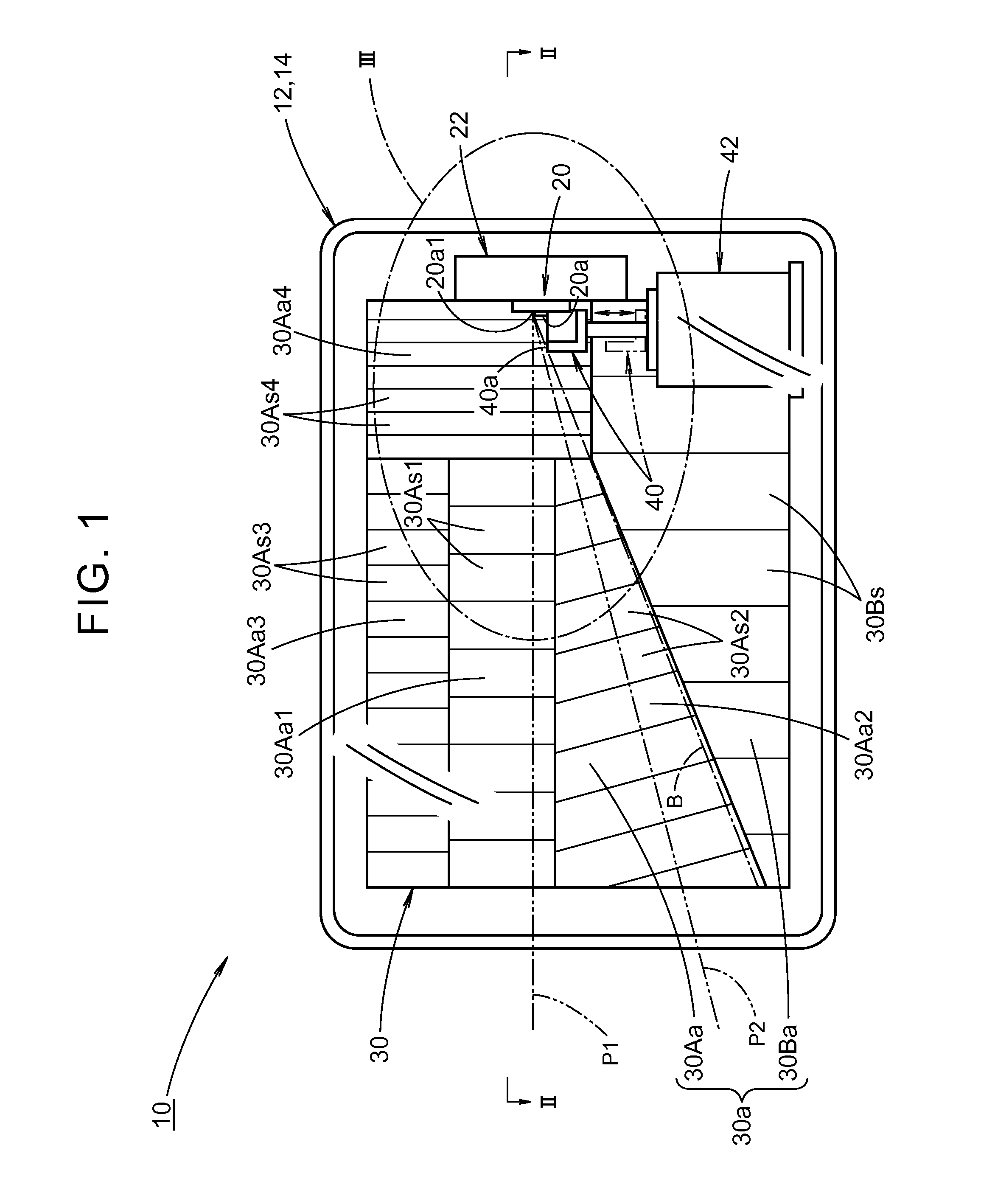
[0024]Hereinbelow, by using the drawings, an embodiment of the invention of the application will be described.

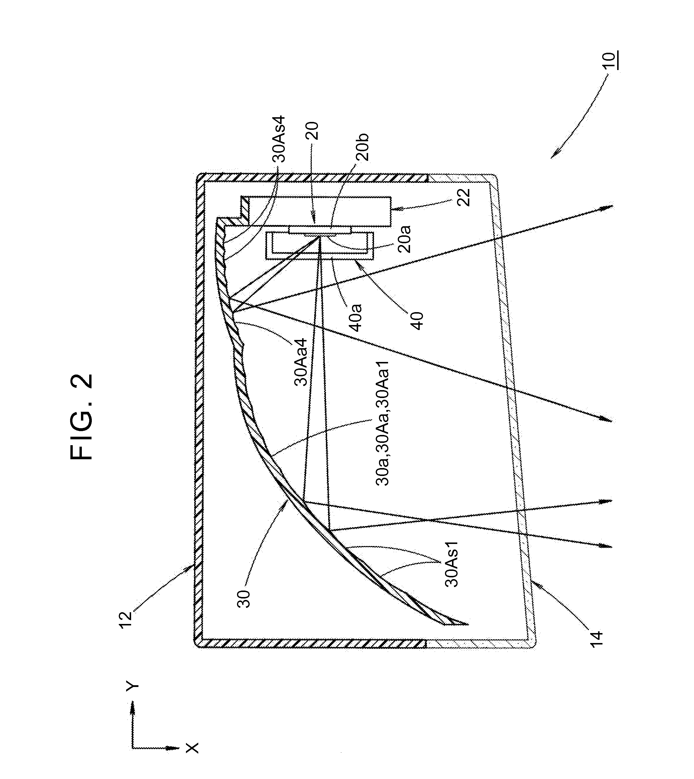
[0025]FIG. 1 is a front view showing a vehicle lamp 10 according to the embodiment of the invention of the application. FIG. 2 is a sectional view taken along the II-II of FIG. 1.

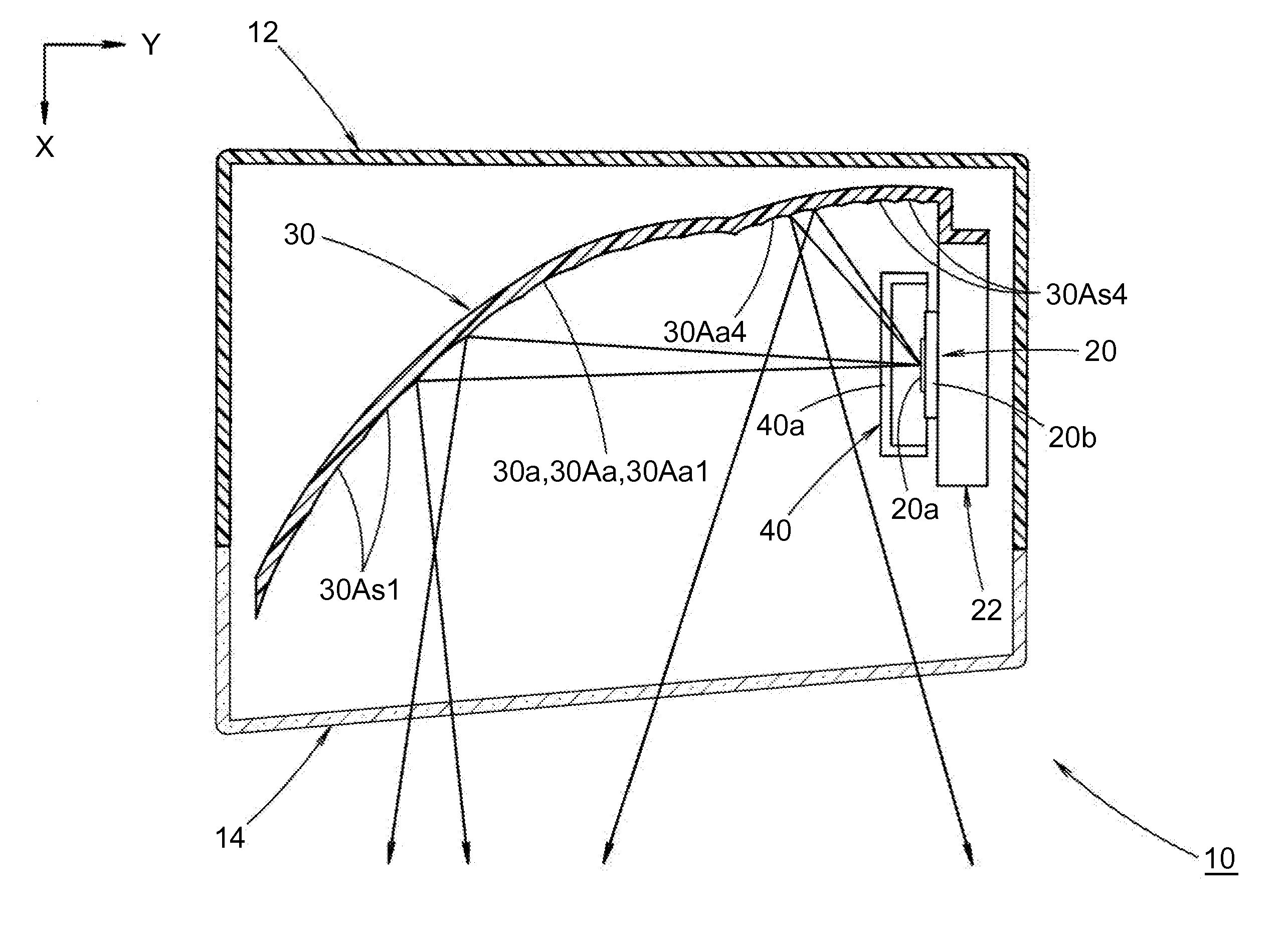
[0026]As shown in these drawings, the vehicle lamp 10 according to the embodiment is a head lamp disposed at a left front end portion of a vehicle, and is configured to selectively perform low beam irradiation and high beam irradiation.

[0027]For the vehicle lamp 10, a direction indicated by X in FIG. 2 is a “forward direction” (the “forward direction” for the vehicle), and a direction indicated by Y in FIG. 2 is a “left direction” orthogonal to the “forward direction” (the “left direction” for the vehicle but a “right direction” when the lamp is viewed from the front).

[0028]In the vehicle lamp 10, a light emitting element 20, a reflector 30 that reflects an emitted light beam from the light emitting...


PUM


Abstract

A vehicle lamp includes a shade movable between a light blocking position and a light blocking release position. A light emitting surface of a light emitting element faces one side in a lateral direction and an upper end edge of the light emitting surface extends in a front-rear direction. A reflective surface of a reflector includes a first reflective area and a second reflective area. A low-beam light distribution pattern having a horizontal cut-off line and an oblique cut-off line is formed by a reflected light beam from the first reflective area when the shade is at the light blocking position, and a high-beam light distribution pattern is formed by the reflected light beams from the first reflective area and the second reflective area when the shade is at the light blocking release position.

Description

[0001]The disclosure of Japanese Patent Application No. 2014-206172 filed on Oct. 7, 2014 including the specification, drawings and abstract is incorporated herein by reference in its entirety.BACKGROUND OF THE INVENTION[0002]1. Field of the Invention[0003]The invention of this application relates to a vehicle lamp configured to selectively perform low beam irradiation and high beam irradiation.[0004]2. Description of Related Art[0005]Conventionally, a vehicle lamp configured to selectively perform low beam irradiation and high beam irradiation by reflecting a light beam from a light emitting element forward using a reflector is available.[0006]Japanese Patent No. 4335621 describes such a vehicle lamp in which a low-beam light distribution pattern having horizontal and oblique cut-off lines is formed by the low beam irradiation.[0007]In the vehicle lamp described in Japanese Patent No. 4335621, the horizontal cut-off line and the oblique cut-off line are formed by turning on separat...

Claims


Application Information

Patent Timeline
Patent Type & Authority Applications(United States)
IPC IPC(8): F21S8/10F21W107/10
CPCF21S48/1784F21Y2101/02F21S48/1376F21Y2115/10F21S41/336F21S41/337F21S41/686F21S41/151F21S41/148
Inventor KINOUCHI, TOSHIYUKI
Owner KOITO MFG CO LTD
Why Eureka
Try Eureka