Guidance system,tools and devices for spinal fixation

Active Publication Date: 2008-06-19
KIC VENTURES LLC +1
View PDF12 Cites 63 Cited by
  • Summary
  • Abstract
  • Description
  • Claims
  • Application Information

AI Technical Summary

Benefits of technology

[0011]Among the advantages of this invention may be one or more of the following. The system allows the fixation elements to be implanted and removed one piece at a time via minimally invasive surge

Problems solved by technology

Improper alignment may result in improper or unstable placement of the fixation element and/or disengagement of the fixation element.
However, achieving and maintaining accurate positioning and guidance of these fixation elements has proven to be quite difficult in practic

Method used


Image

  • Guidance system,tools and devices for spinal fixation
  • Guidance system,tools and devices for spinal fixation
  • Guidance system,tools and devices for spinal fixation

Examples


Embodiment Construction

[0056]The present invention relates to a system and a method for spinal fixation, and in particular, to a guidance system, insertion tools and devices for spinal fixation.

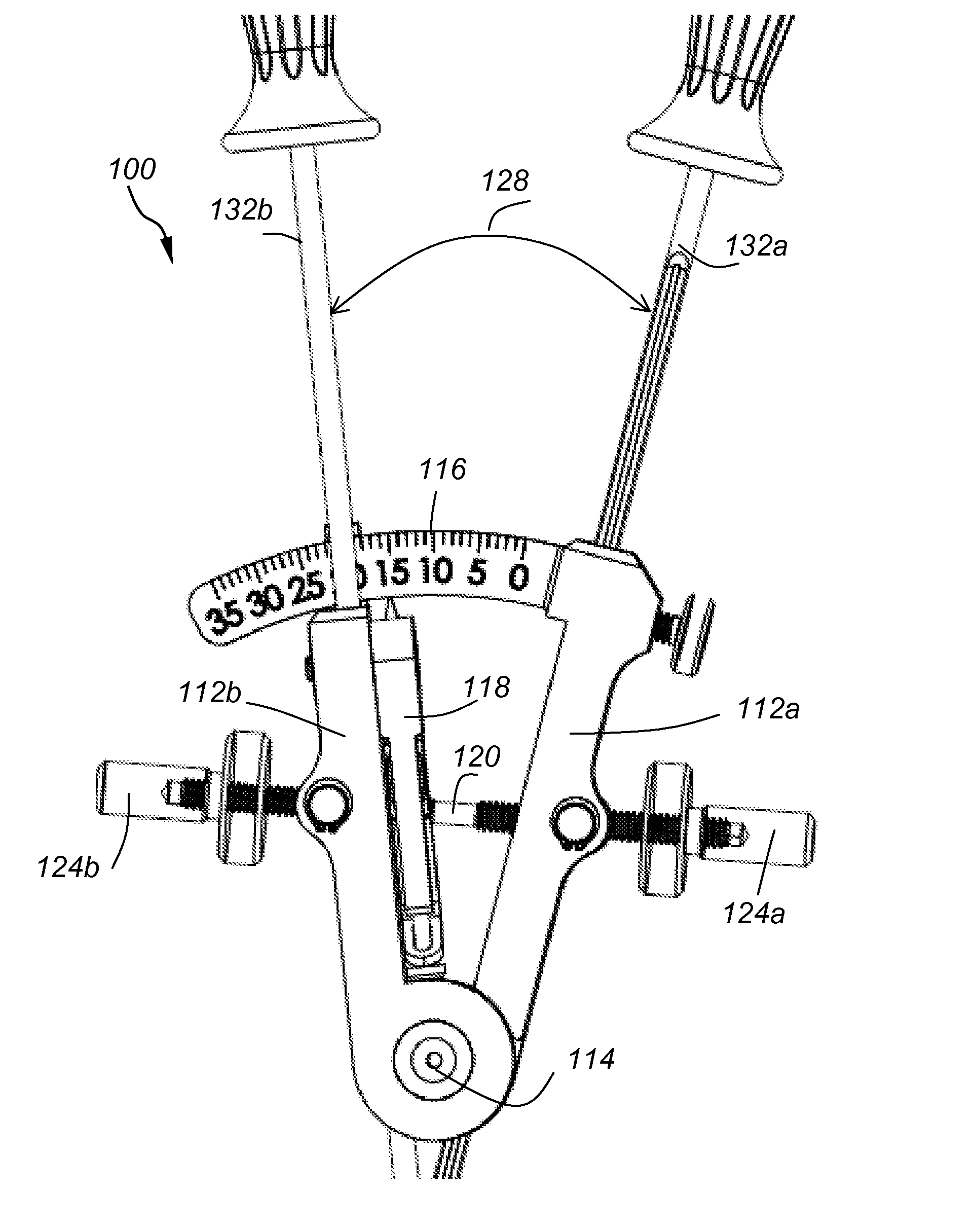
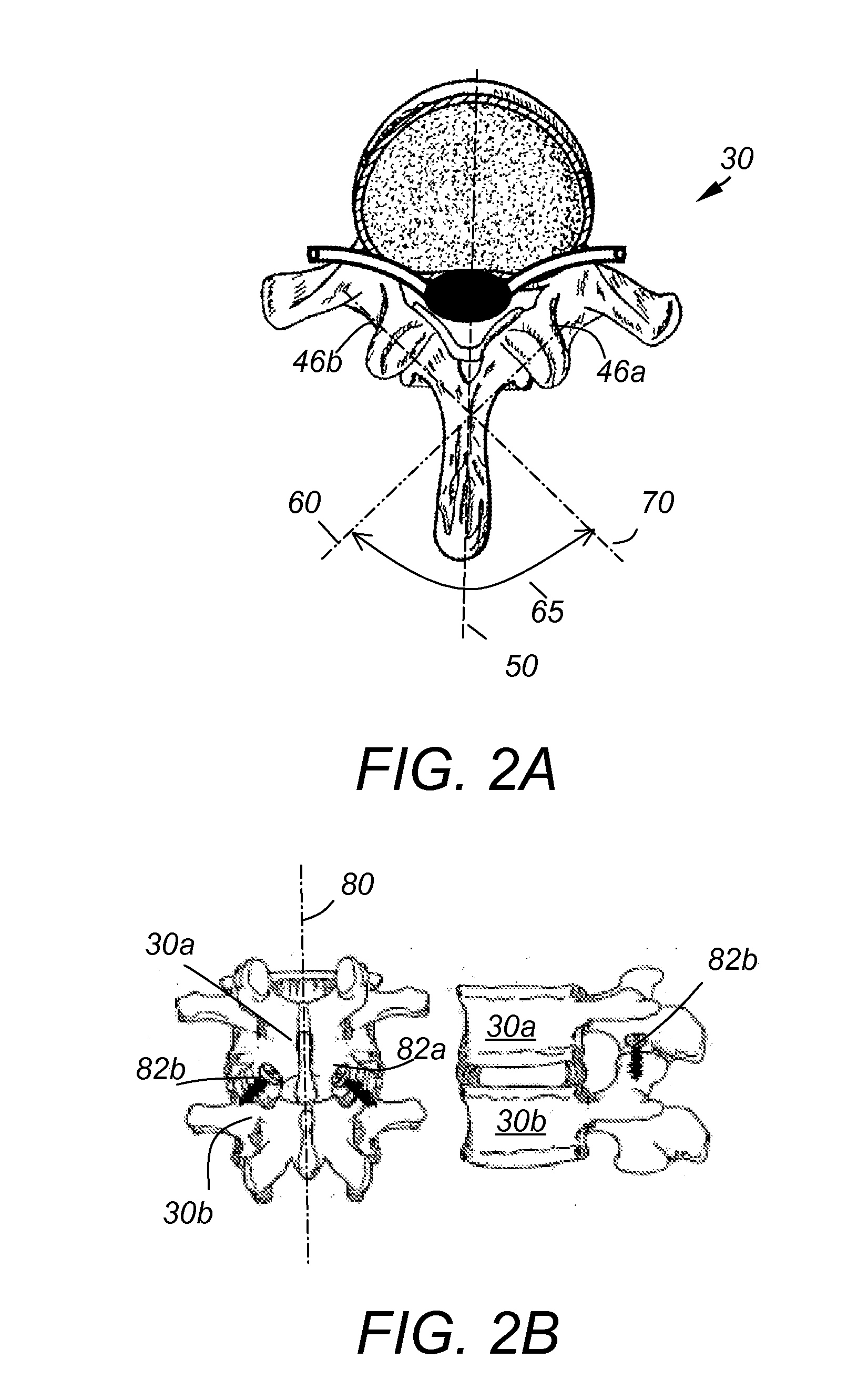
[0057]Referring to FIG. 2A, 2B, spinal fixation elements 82a, 82b are used to secure together first and second facet joints 46a, 46b. The spinal fixation elements 82a, 82b are inserted along the directions 60, 70, respectively. Directions 60, 70 form an angle 65 between them. In most cases, directions 60, 70 are symmetrically positioned to the left and right of the spinal midline 80 which is perpendicular to the dichotome 50 of angle 65. In this example, fixation elements 82a, 82b are facet screws and are placed in a trans-facet way for connecting adjacent vertebras 30a, 30b. In other examples, fixation elements 82a, 82b, may be staples, wires, or pins, and they may connect adjacent or non-adjacent vertebras via trans-facet, trans-laminar, trans-facet-pedicular, trans-pedicular, or through any other vertebral locat...


PUM


Abstract

A system for attaching first and second spine fixation elements at a predetermined angle relative to each other to first and second locations of a vertebra, respectively includes first and second guide arms pivotally connected to each other at a first pivot point and configured to pivot around a pivot axis passing through the first pivot point, and first and second guide tubes passing through first and second elongated through-bore openings formed in the first and second guide arms, respectively, and forming an X-structure as they exit the first and second through-bore openings.

Description

CROSS REFERENCE TO RELATED CO-PENDING APPLICATIONS[0001]This application claims the benefit of U.S. provisional application Ser. No. 60 / 870,251 filed Dec. 15, 2006 and entitled “GUIDANCE SYSTEM, TOOLS AND DEVICES FOR SPINAL FIXATION”, the contents of which are expressly incorporated herein by reference.[0002]This application is also a continuation in part of U.S. application Ser. No. 11 / 779526 filed on Jul. 18, 2007 and entitled “SYSTEM AND METHOD FOR SPINE FIXATION” the contents of which are expressly incorporated herein by reference.FIELD OF THE INVENTION[0003]The present invention relates to a system and method for spinal fixation, and in particular to a guidance system, insertion tools and devices for spinal fixation.BACKGROUND OF THE INVENTION[0004]The human spine comprises individual vertebras 30 (segments) that are connected to each other to form a spinal column 29, shown in FIG. 1. Referring to FIGS. 1B and 1C, each vertebra 30 has a cylindrical bony body (vertebral body) 32...

Claims


Application Information

Patent Timeline
IPC IPC(8): A61B17/58
CPCA61B17/1637A61B17/1757A61B17/864A61B17/8695A61B17/7082A61B2017/3445A61B2019/467A61B17/7064A61B17/8897A61B2090/067
Inventor CHIN, KINGSLEY RICHARDCHANG, CHRISTOPHER A.CORRAO, ERNIE
Owner KIC VENTURES LLC
Why Eureka
Try Eureka