Supercharge Your Innovation With Domain-Expert AI Agents!

Magnetic current sensor calibration system and method

a current sensor and calibration system technology, applied in the field of current sensors, can solve the problems of many relatively high accuracy, and high cost of robust current sensors

Inactive Publication Date: 2016-04-21
HONEYWELL INT INC
View PDF3 Cites 7 Cited by
  • Summary
  • Abstract
  • Description
  • Claims
  • Application Information

AI Technical Summary

Benefits of technology

The patent describes a magnetic current sensor calibration system that includes a substrate with multiple sensors mounted on its surface. The substrate has two calibration conductors, one on each surface, which are used to create magnetic fields for calibration purposes. The system also includes a controller that can adjust the sensors' gain and offset, and measure the outputs of each sensor. The technical effect of this system is to provide a more accurate and reliable calibration for magnetic current sensors.

Problems solved by technology

Regardless of the technique that is employed, many current sensors that are used to measure relatively large current magnitudes operate in challenging environments.
For example, these current sensors may be exposed to relatively large temperature variations, relatively high and / or low temperatures, and to vibration.
Unfortunately, many relatively high-accuracy, robust current sensors can be costly, and many rely on relatively cumbersome calibration procedures.

Method used


Image

  • Magnetic current sensor calibration system and method
  • Magnetic current sensor calibration system and method
  • Magnetic current sensor calibration system and method

Examples


Embodiment Construction

[0015]The following detailed description is merely exemplary in nature and is not intended to limit the invention or the application and uses of the invention. As used herein, the word “exemplary” means “serving as an example, instance, or illustration.” Thus, any embodiment described herein as “exemplary” is not necessarily to be construed as preferred or advantageous over other embodiments. All of the embodiments described herein are exemplary embodiments provided to enable persons skilled in the art to make or use the invention and not to limit the scope of the invention which is defined by the claims. Furthermore, there is no intention to be bound by any expressed or implied theory presented in the preceding technical field, background, brief summary, or the following detailed description.

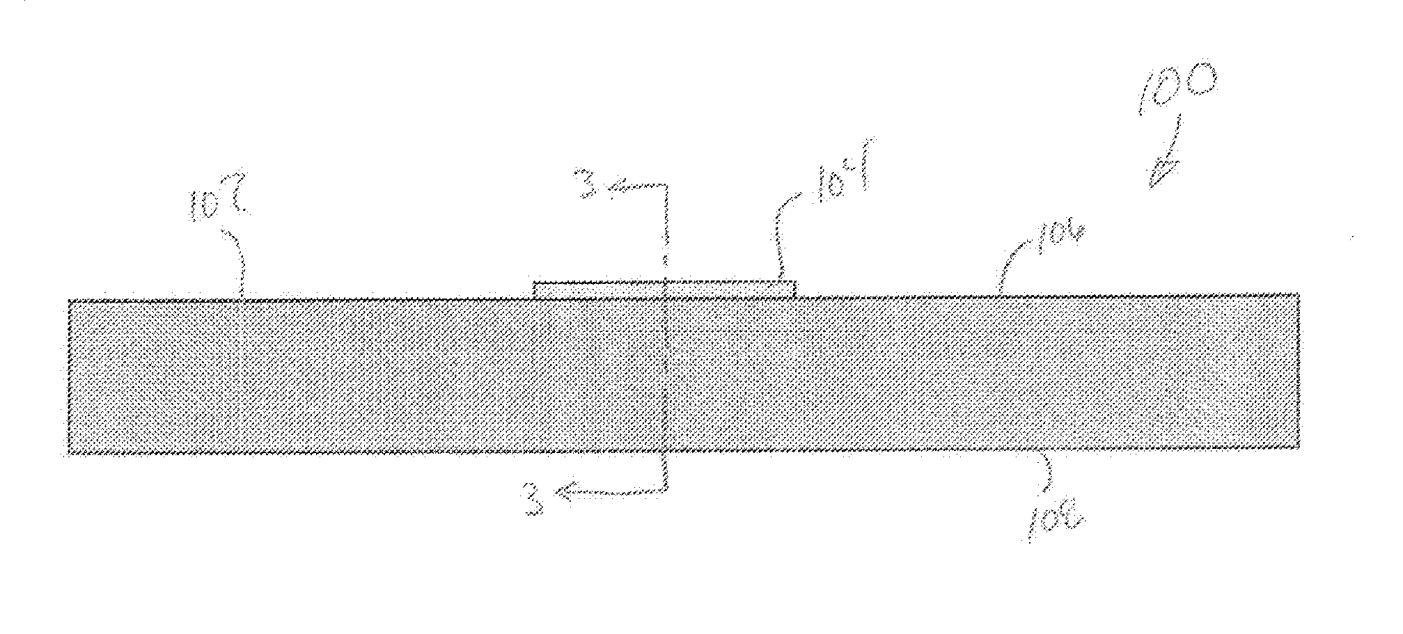
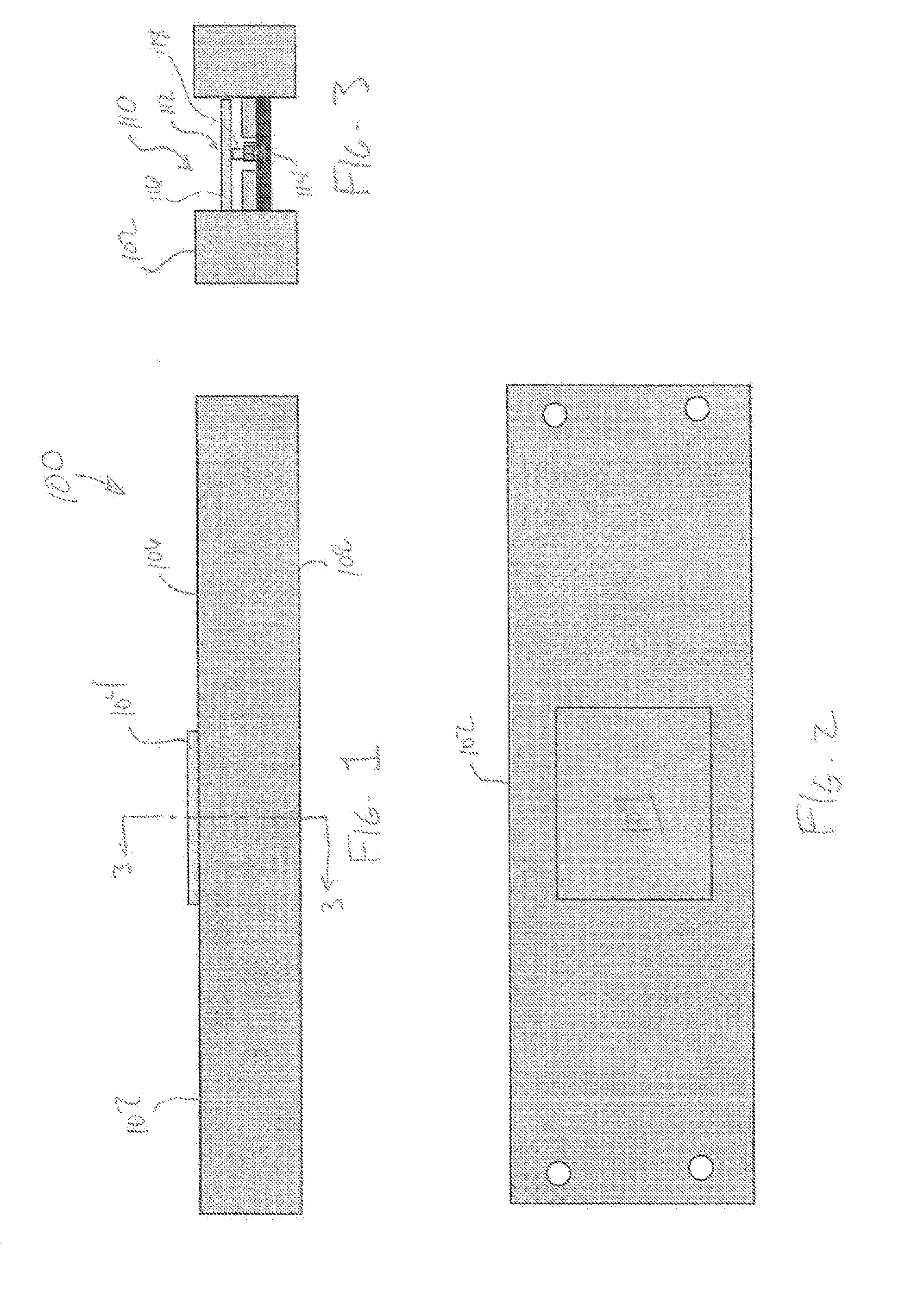
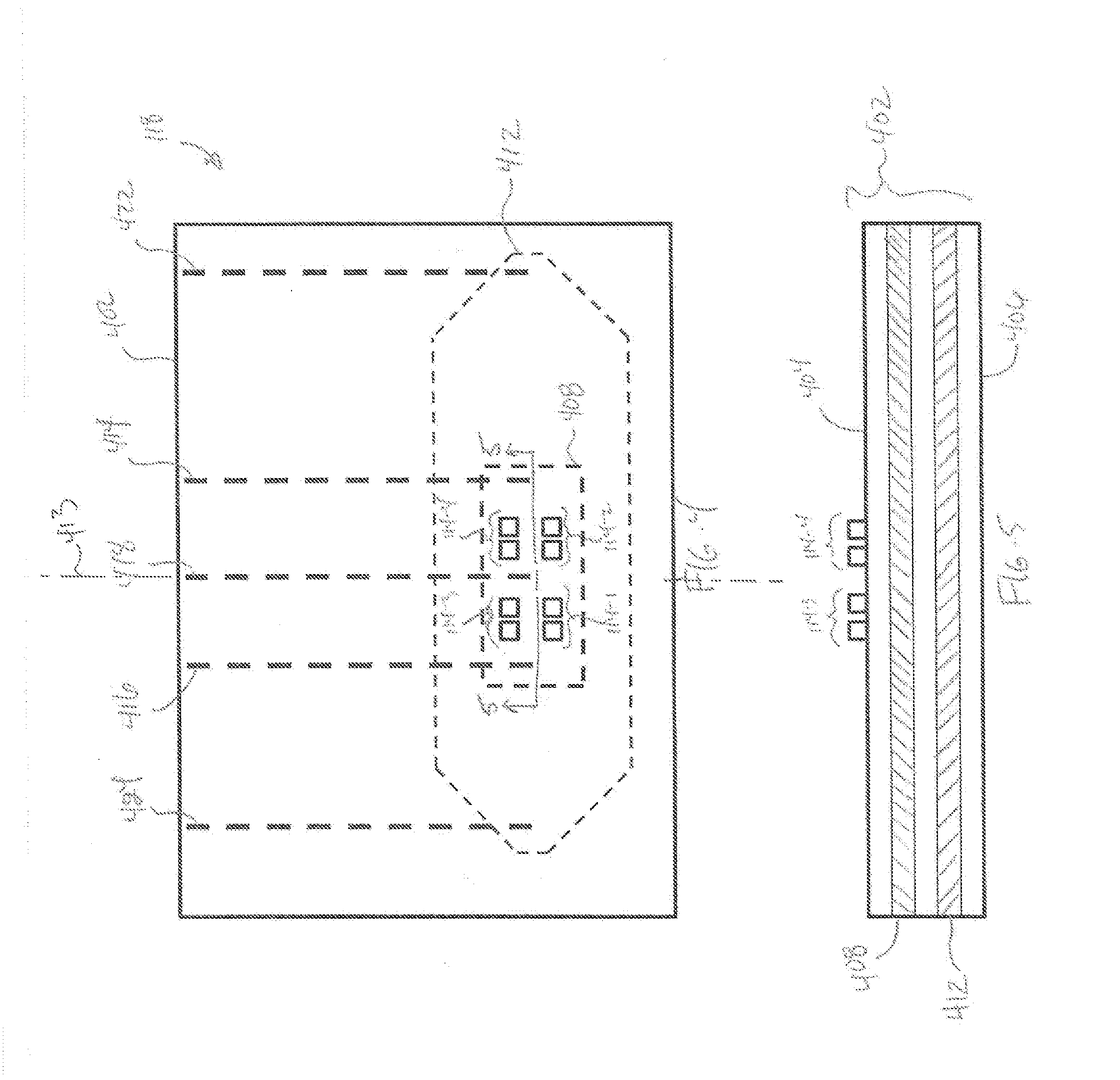
[0016]Referring now to FIGS. 1-3, side, top, and cross section schematic views, respectively, of a current sensor system 100 are depicted. The depicted system includes a conductor 102 and a cur...


PUM


Abstract

A magnetic current sensor calibration system includes a plurality of sensors and a substrate. The substrate has a first surface and a second surface, and the sensors are mounted on the first surface. The substrate includes a bipolar calibration conductor and a unipolar calibration conductor. The bipolar calibration conductor is spaced apart from the plurality of sensors and is disposed between the first and second surfaces. The unipolar calibration conductor is spaced apart from the plurality of sensors and the bipolar calibration conductor, and is disposed between the first and second surfaces.

Description

CROSS-REFERENCE TO RELATED APPLICATIONS[0001]This application claims the benefit of U.S. Provisional Application No. 62 / 064,054 filed Oct. 15, 2014.TECHNICAL FIELD[0002]The present invention generally relates to current sensors, and more particularly relates to systems and methods for calibrating magnetic current sensors.BACKGROUND[0003]Current sensors are used in myriad systems to monitor the magnitude of electrical current being supplied to or drawn by various electrical loads. Numerous techniques have been developed for sensing electrical current. One particular technique, which is used to measure relatively large current magnitudes, involves measuring the magnetic field that is generated when electrical current flows in a conductor.[0004]Regardless of the technique that is employed, many current sensors that are used to measure relatively large current magnitudes operate in challenging environments. For example, these current sensors may be exposed to relatively large temperatur...

Claims


Application Information

Patent Timeline
IPC IPC(8): G01R35/00G01R15/20
CPCG01R15/20G01R35/005G01R15/205G01R33/0005G01R33/0017G01R33/0035G01R33/06
Inventor PECZALSKI, ANDYREZACHEK, TOM
Owner HONEYWELL INT INC
Features
  • R&D
  • Intellectual Property
  • Life Sciences
  • Materials
  • Tech Scout
  • Unparalleled Data Quality
  • Higher Quality Content
  • 60% Fewer Hallucinations
Learn More