

Magnetic compass
a magnetic compass and compass technology, applied in the field of magnetic compass, can solve the problems of increasing the number of sensors, difficult to calculate the correct direction, complicated operations, etc., and achieve the effect of suppressing the effect of magnetic dip, accurate measurement of azimuth, and simple structur
- Summary
- Abstract
- Description
- Claims
- Application Information
AI Technical Summary
Benefits of technology
Problems solved by technology
Method used
Image

Examples
first embodiment
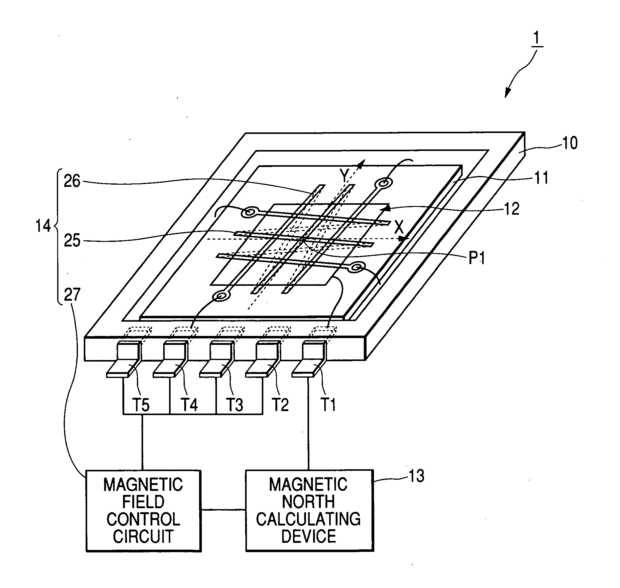
[0027] a magnetic compass according to the present invention will now be described with reference to FIGS. 1 to 6.
[0028] As illustrated in FIG. 1, a magnetic compass 1 according to the present embodiment includes a package 10, a substrate (a base material) 11 accommodated in the package 10, a two-axis sensor 12 for, when the X and Y axes are orthogonal to each other on the substrate 11, detecting the magnetic fields of the respective axes, a magnetic north calculating device (an azimuth measuring device) 13 that is an electronic circuit for calculating the direction of the magnetic north based on the magnetic fields detected by the two-axis sensor 12, and a rotating magnetic field generating device 14 for generating a rotating magnetic field having a uniform strength using the reference point P1 that is the intersection between the two axes as a rotating center.
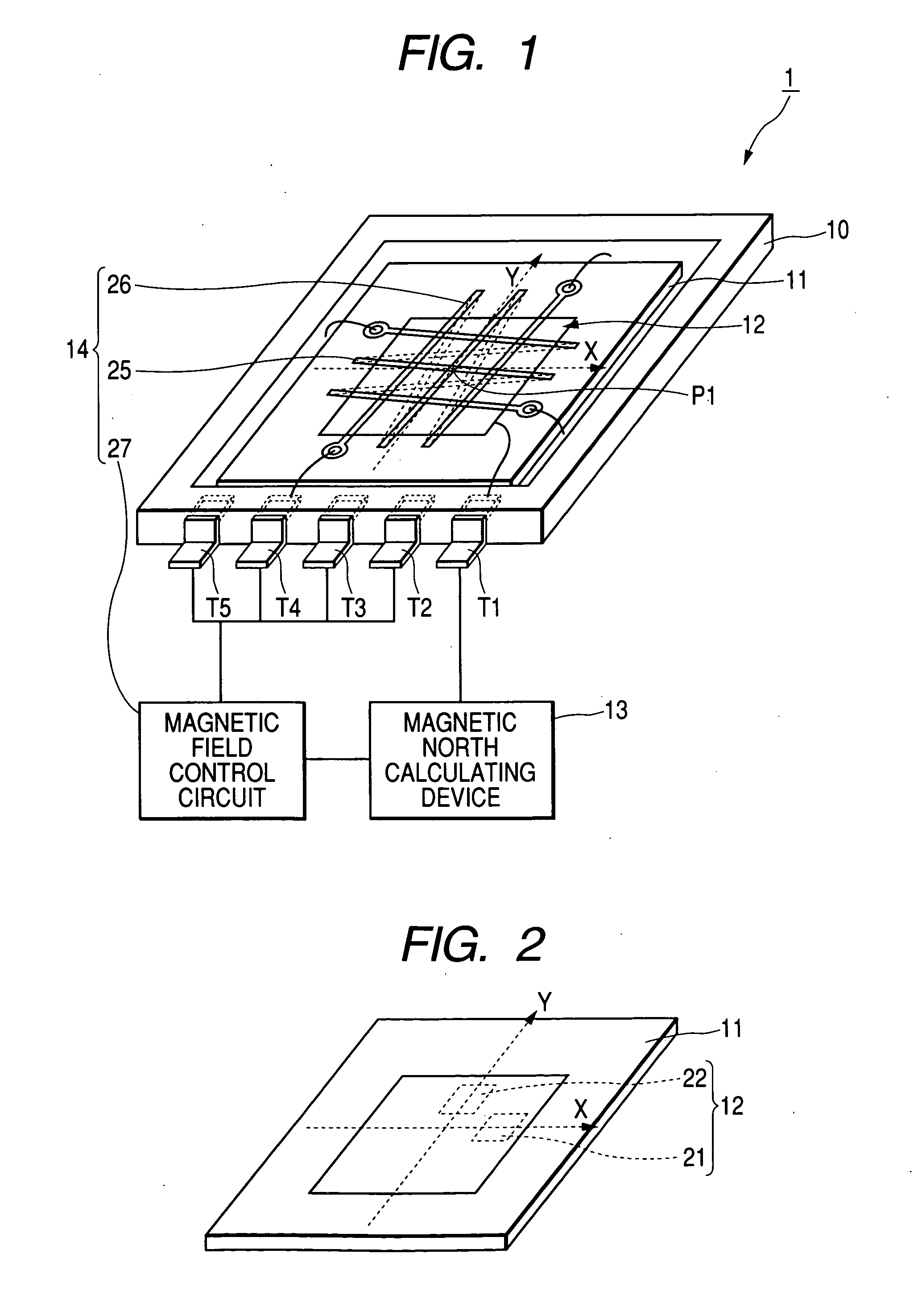
[0029] As illustrated in FIG. 2, the two-axis sensor 12 includes an X axis magnetic sensor 21 composed of a Hall element, ...
second embodiment
[0050] Next, a second embodiment will be described with reference to FIG. 7.
[0051] The basic structure of the second embodiment is the same as that of the above-described first embodiment, and the second embodiment is obtained by adding different components to the first embodiment. Therefore, in FIG. 7, the same members as those of FIG. 1 are denoted by the same reference numerals and description thereof will be omitted.
[0052] Difference between the second embodiment and the first embodiment lies in that, meanwhile the rotating magnetic field generating device 14 is composed of the X axis coil 25, the Y axis coil 26, and the magnetic field control circuit 27 according to the first embodiment, in a magnetic compass 30 according to the second embodiment, a rotating magnetic field generating device 31 includes a permanent magnet 32 whose magnetic poles are arranged from the reference point P1 toward a radial direction on the plane of the substrate 11 and a rotation driving portion 33 ...
PUM
 Abstract
Description
Claims
Application Information