Method of controlling a brushless permanent-magnet motor

a permanent magnet, brushless technology, applied in the direction of synchronous motor starters, electronic commutators, electrical apparatus, etc., can solve the problem of sensitive current and thus power that is driven into the winding, and achieve the effect of improving the efficiency of the motor, shortening the length of each electrical half-cycle, and relatively large back em

Active Publication Date: 2014-12-18
DYSON TECH LTD
View PDF4 Cites 7 Cited by
  • Summary
  • Abstract
  • Description
  • Claims
  • Application Information

AI Technical Summary

Benefits of technology

[0005]At speeds greater than 50 krpm, the length of each electrical half-cycle is relatively short and the magnitude of the back EMF is relatively large. Both of these factors would suggest that advanced commutation is necessary in order to drive sufficient current and thus power into the phase winding in order to maintain such speeds. However, the applicant has identified that, once the motor is at this speed, improvements in the efficiency of the motor may be achieved by retarding commutation. For a permanent-magnet motor, the torque-to-current ratio is at a maximum when the waveform of the phase current matches that of the back EMF. Improvements in the efficiency of the motor are therefore achieved by shaping the waveform of the phase current such that it better matches the waveform of the back EMF. In instances for which the phase current rises faster than the back EMF at around zero-crossings in the back EMF, advanced commutation would cause the phase current to quickly lead the back EMF. By retarding commutation until after each zero-crossing in the back EMF, the rise in the phase current may be made to more closely follow that of the back EMF. As a result, the efficiency of the motor may be improved.
[0027]The method may comprise controlling the motor in the manner described in any one of the preceding paragraphs when operating over a speed range that spans at least 5 krpm, and more preferably at least 10 krpm. As a result, improvements in the efficiency of the motor may be achieved over a relatively large speed range.

Problems solved by technology

Additionally, the amount of current and thus power that is driven into the winding is sensitive to changes in the supply voltage and / or the motor speed.

Method used


Image

  • Method of controlling a brushless permanent-magnet motor
  • Method of controlling a brushless permanent-magnet motor
  • Method of controlling a brushless permanent-magnet motor

Examples


Embodiment Construction

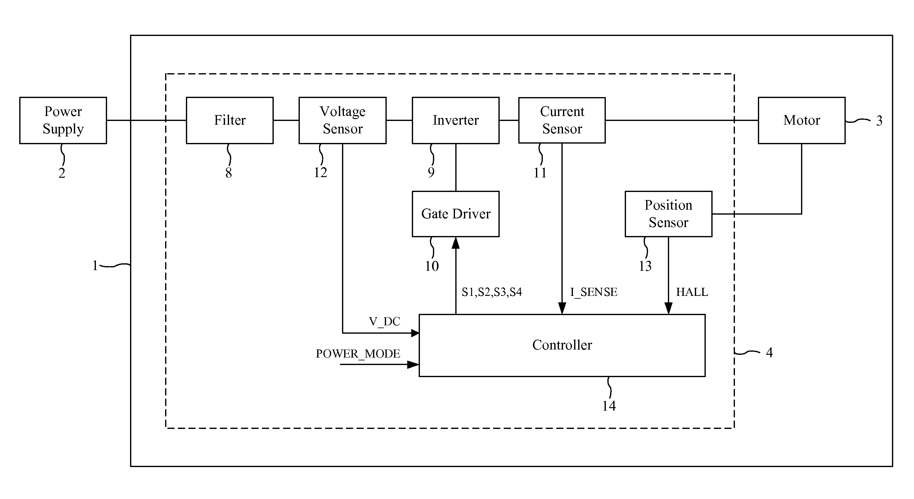
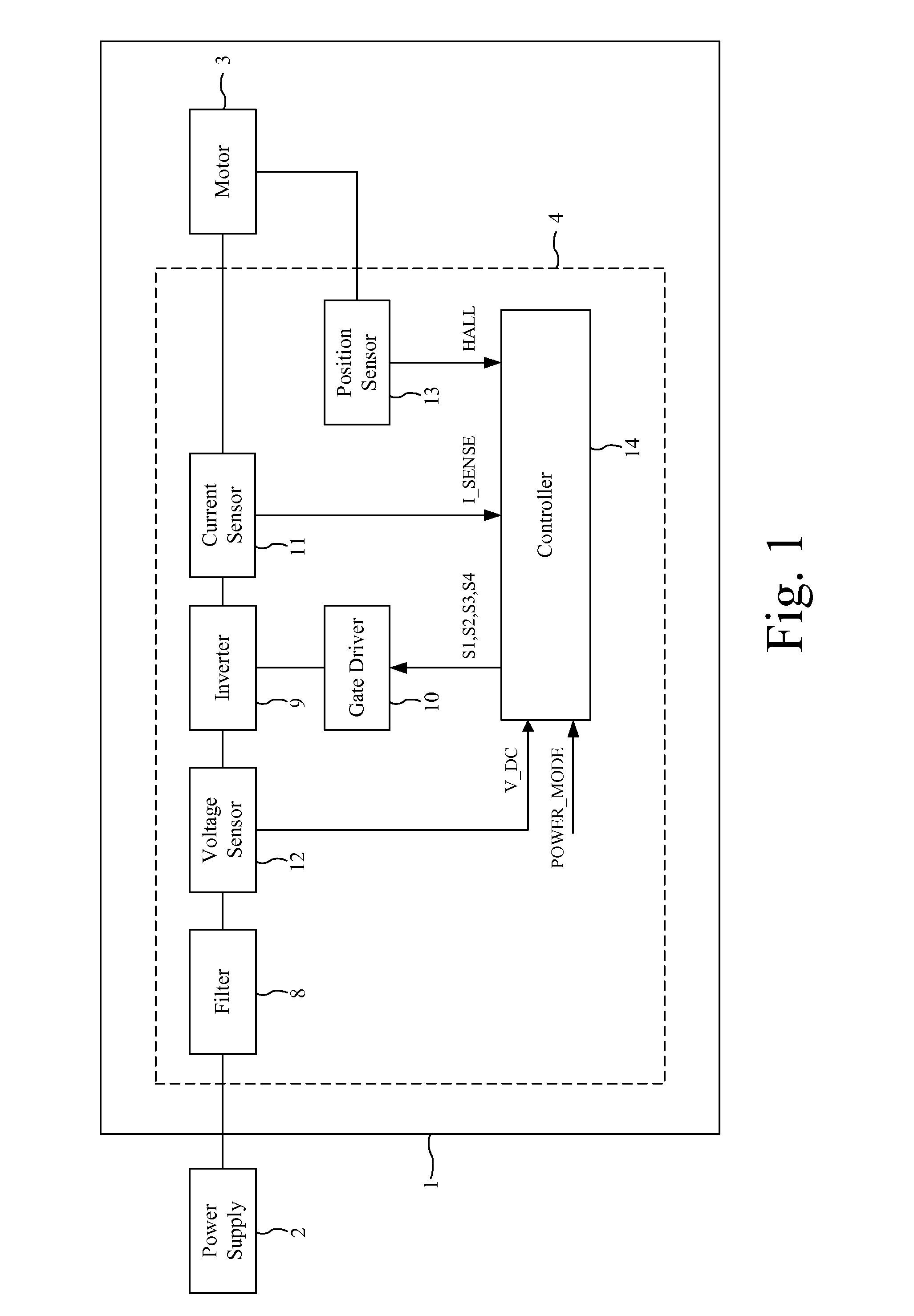
[0037]The motor assembly 1 of FIGS. 1 and 2 is powered by a DC power supply 2 and comprises a brushless motor 3 and a control circuit 4.

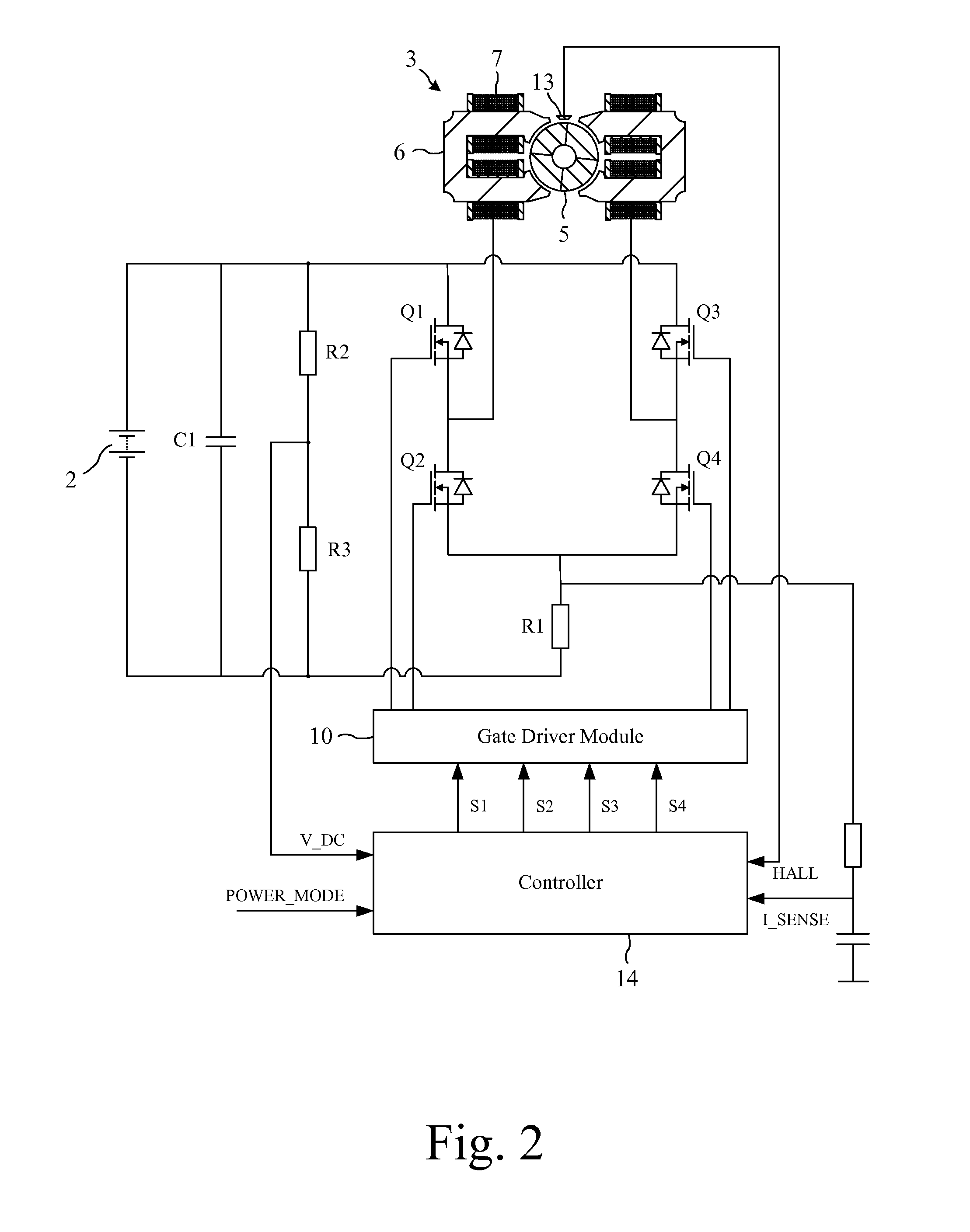
[0038]The motor 3 comprises a four-pole permanent-magnet rotor 5 that rotates relative to a four-pole stator 6. Conductive wires wound about the stator 6 are coupled together to form a single phase winding 7.

[0039]The control circuit 4 comprises a filter 8, an inverter 9, a gate driver module 10, a current sensor 11, a voltage sensor 12, a position sensor 13, and a controller 14.

[0040]The filter 8 comprises a link capacitor C1 that smoothes the relatively high-frequency ripple that arises from switching of the inverter 9.

[0041]The inverter 9 comprises a full bridge of four power switches Q1-Q4 that couple the phase winding 7 to the voltage rails. Each of the switches Q1-Q4 includes a freewheel diode.

[0042]The gate driver module 10 drives the opening and closing of the switches Q1-Q4 in response to control signals received from the controller 14.

[004...


PUM


Abstract

A method of controlling a brushless permanent-magnet motor. The method includes commutating a winding of the motor at times that are retarded relative to zero-crossings of back EMF in the winding.

Description

REFERENCE TO RELATED APPLICATION[0001]This application claims priority of United Kingdom Application Nos. 1310574.7 and 1310572.1, filed Jun. 13, 2013, the entire contents of which are incorporated herein by reference.FIELD OF THE INVENTION[0002]The present invention relates to a method of controlling a brushless permanent-magnet motor.BACKGROUND OF THE INVENTION[0003]There is a growing need to improve the efficiency of brushless permanent-magnet motors.SUMMARY OF THE INVENTION[0004]The present invention provides a method of controlling a brushless permanent-magnet motor, the method comprising commutating a winding of the motor at times that are retarded relative to zero-crossings of back EMF in the winding when operating at speeds greater than 50 krpm.[0005]At speeds greater than 50 krpm, the length of each electrical half-cycle is relatively short and the magnitude of the back EMF is relatively large. Both of these factors would suggest that advanced commutation is necessary in or...

Claims


Application Information

Patent Timeline
Patent Type & Authority Applications(United States)
IPC IPC(8): H02P6/14
CPCH02P6/147H02P6/157H02P6/085
Inventor CELIK, TUNCAY
Owner DYSON TECH LTD
Why Eureka
Try Eureka