
Microchip sensor for continuous monitoring of regional blood flow

a microchip sensor and blood flow technology, applied in the field of microchip sensor for continuous monitoring of regional blood flow, can solve the problem that few of these techniques lend themselves to routine clinical application

Inactive Publication Date: 2016-04-28
THE FEINSTEIN INST FOR MEDICAL RES
View PDF2 Cites 6 Cited by
  • Summary
  • Abstract
  • Description
  • Claims
  • Application Information

AI Technical Summary

Benefits of technology

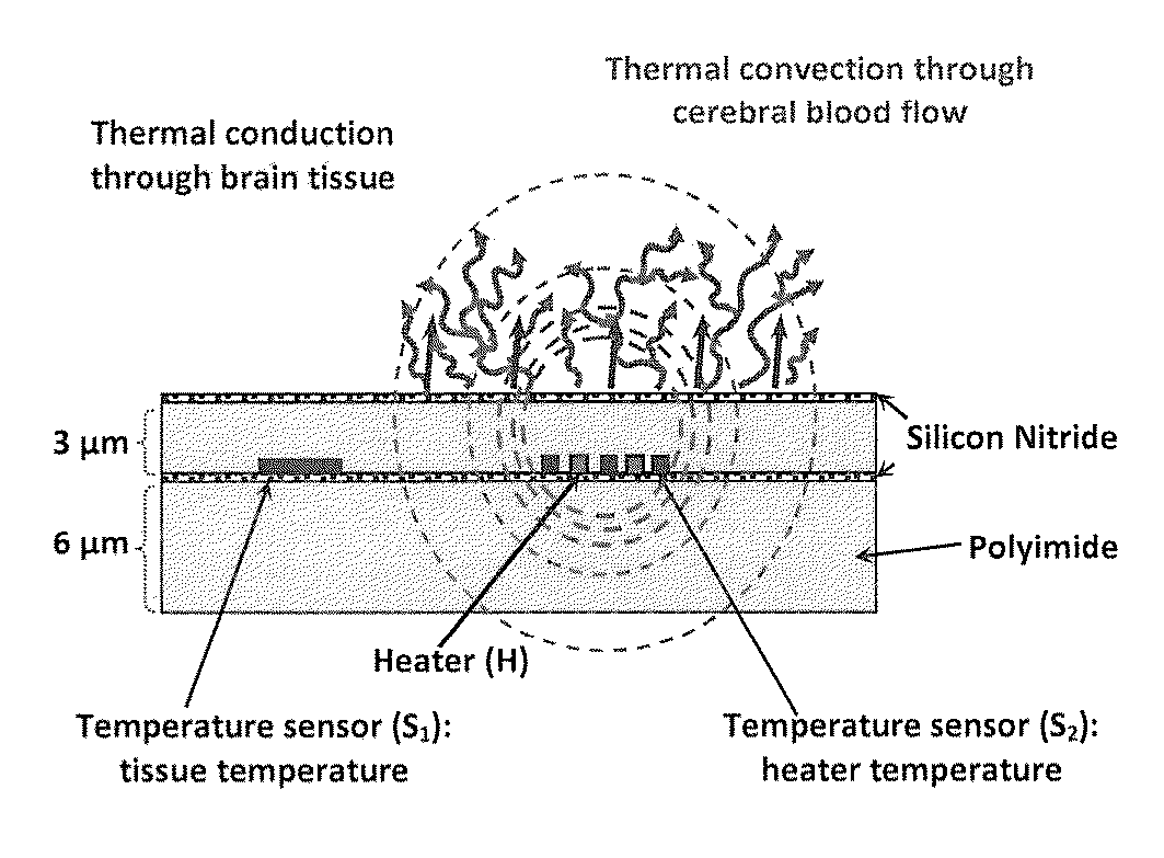
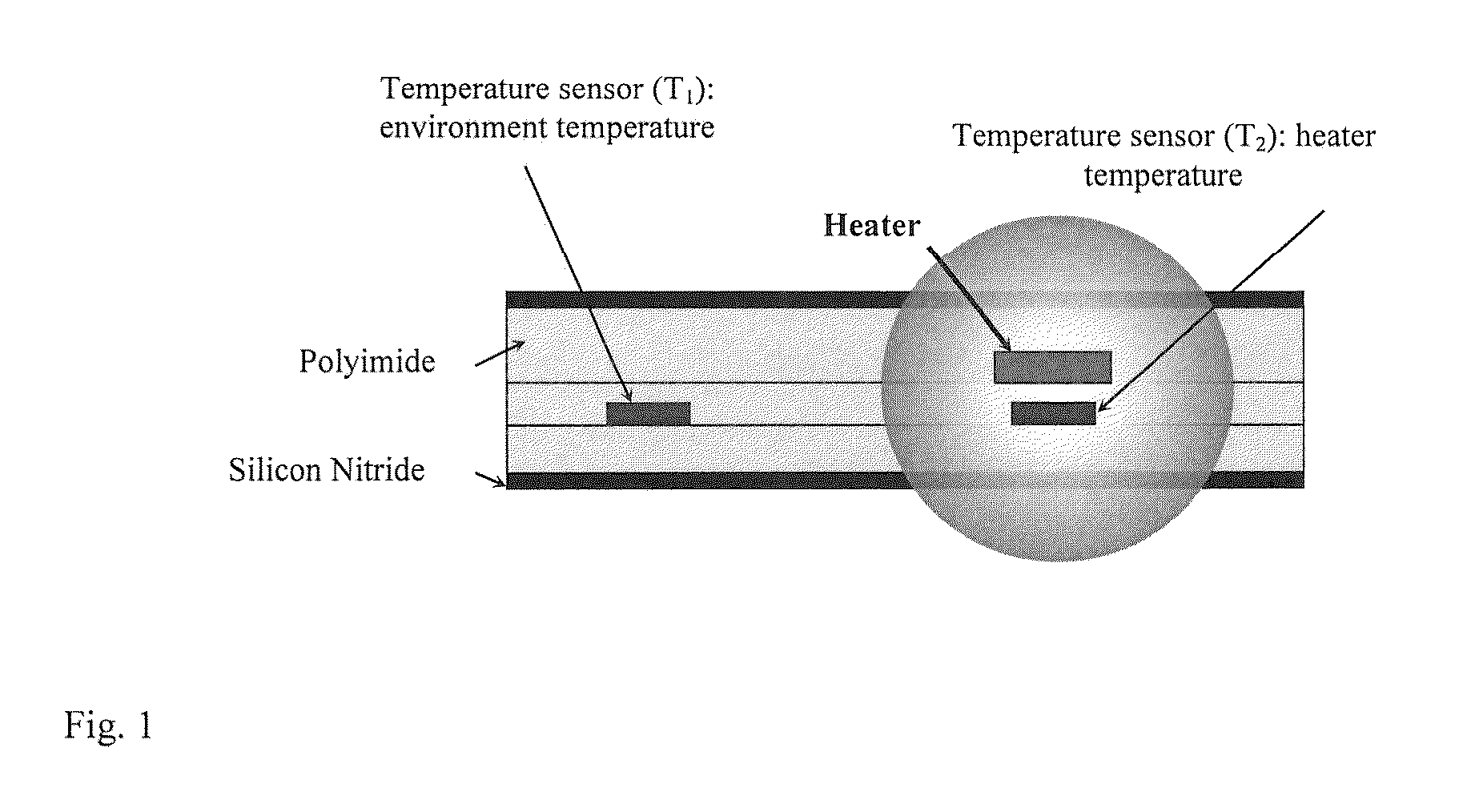
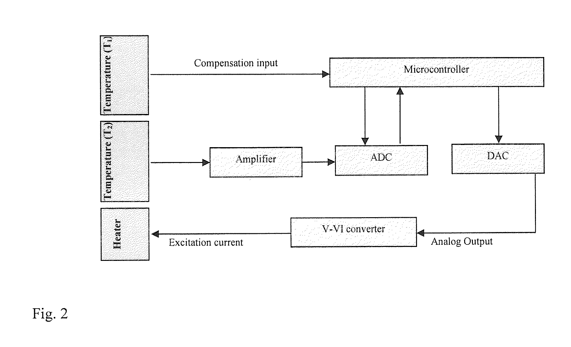
This patent describes a blood flow meter that can be used to monitor blood flow in a biological tissue. It involves a flexible substrate and a heater element that can be controlled to heat the substrate. A temperature sensor is also included to measure the temperature of the tissue. The blood flow meter can provide data on the blood flow in the tissue in real-time. The patent also describes an array of two blood flow meters that can be placed on the same flexible substrate layers, with the microelectrodes of each meter being positioned in a way that they are outside the thermal influence field of the heater of the other meter. The invention has various applications such as monitoring blood flow in a subject's tissue or skin.

Problems solved by technology

However, few of these techniques lend themselves to routine clinical application due to enduring technical drawbacks.

Method used


Image

  • Microchip sensor for continuous monitoring of regional blood flow
  • Microchip sensor for continuous monitoring of regional blood flow
  • Microchip sensor for continuous monitoring of regional blood flow

Examples


Embodiment Construction

[0024]A blood flow meter is provided for monitoring blood flow in a biological tissue comprising (a) a flow sensor comprising a first microelectrode, which flow sensor is capable of being heated by (b) a heater element positioned within 0.5 μm-100 μm of at least a portion of (a), and (c) a temperature sensor comprising a second microelectrode, wherein (a) and (c) are arranged on a flexible substrate and wherein (b) is positioned relative to (c) such that when (a) is heated by (b) to a stable target temperature of 0.5° C. to 3° C. above the temperature of the biological tissue in which the blood flow meter is situated, (c) is not within the thermal influence field generated by (b).

[0025]In an embodiment, the flexible substrate comprises at least 5 (five) layers.

[0026]In an embodiment, at least two layers of the flexible substrate comprise a flexible polymer. In an embodiment, at least three layers of the flexible substrate comprise a flexible polymer. In an embodiment, at least two l...


PUM


Abstract

A sensor is provided available for continuous monitoring of regional blood flow in a tissue, including cerebral tissue. Methods of monitoring regional blood flow using the sensor as well as systems and computer readable medium therefor are also provided.

Description

CROSS-REFERENCE TO RELATED APPLICATIONS[0001]This application claims benefit of U.S. Provisional Application No. 62 / 068,079, filed Oct. 24, 2014, the contents of which are hereby incorporated by reference.STATEMENT OF GOVERNMENT SUPPORT[0002]This invention was made with government support under grant number W81XWH-1-09 awarded by the U.S. Department of Defense. The government has certain rights in the invention.BACKGROUND OF THE INVENTION[0003]Throughout this application various patents and other publications are referred to in parenthesis. Full citations for the references may be found at the end of the specification. The disclosures of these patents and publications are hereby incorporated by reference in their entirety into the subject application to more fully describe the art to which the subject invention pertains.[0004]The common mechanism for brain injury-induced neuronal loss is inadequate cerebral blood flow (CBF) for the neurons. During pathological conditions such as tra...

Claims


Application Information

Patent Timeline
Patent Type & Authority Applications(United States)
IPC IPC(8): A61B5/026
CPCA61B5/026A61B5/01A61B2560/0242A61B2560/0252A61B2562/164
Inventor NARAYAN, RAJ K.LI, CHUNYAN
Owner THE FEINSTEIN INST FOR MEDICAL RES
Learn More