Method for transmitting power headroom report in network supporting interworkings between multiple communication systems, and apparatus therefor

Active Publication Date: 2016-04-28
LG ELECTRONICS INC
View PDF7 Cites 25 Cited by
  • Summary
  • Abstract
  • Description
  • Claims
  • Application Information

AI Technical Summary

Benefits of technology

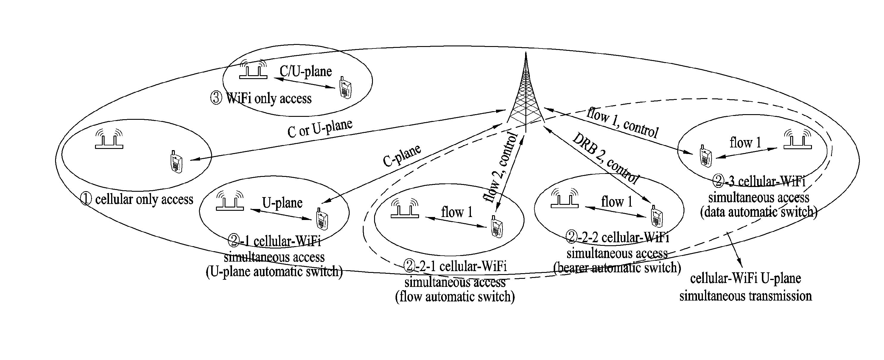
[0011]In case of a UE, which has accessed a cellular network and a WiFi network at the same time, the UE is able to efficiently control transmit power of a UE capable of simultaneously transmitting data to the cellular network and the WiFi network using a power headroom report on wireless LAN-related transmit power proposed by the presen

Problems solved by technology

However, although the multi-RAT UE has the capability to access two or more RATs, the multi-RAT UE cannot simultaneously access multiple RATs.
In other words, although a current UE has multi-RAT capability, the UE cannot simultaneously transmit and receive data through different RATs.
Since the aforementioned legacy m

Method used


Image

  • Method for transmitting power headroom report in network supporting interworkings between multiple communication systems, and apparatus therefor
  • Method for transmitting power headroom report in network supporting interworkings between multiple communication systems, and apparatus therefor
  • Method for transmitting power headroom report in network supporting interworkings between multiple communication systems, and apparatus therefor

Examples


case 1

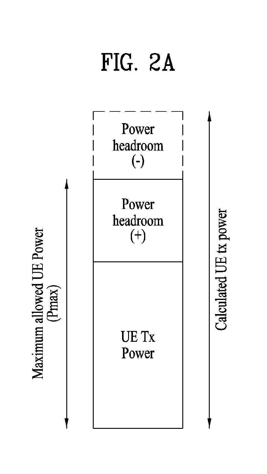
[0122] If CA is not configured, a UE is able to additionally transmit a PH of a new type in consideration of PUSCH and transmit power (PWLAN) of 802.11. The PH of the new type can be represented as follows.

Phtype new(i)=Pmax−{10 log10(Mpusch(i))+Po pusch(j)+α(j)·PL+Δtf(i)+f(i)+PWLAN}

[0123]In this case, Pmax=Pcmax+Pwmax or Pmax=Pcmax+local Pwmax.

[0124]PWLAN corresponds to WLAN actual transmit power strength of same time (estimated transmit power). This field indicates actual power measured from an output of an antenna connector in this TTI.

[0125]A MAC control element for the PH may use a format defined in the aforementioned Method 1 as it is. It is able to use WLAN power headroom included in the aforementioned WLAN PH MAC control element. Or, it is able to define a MAC control element of a new format for a WLAN-cellular interworking UE. WLAN-cellular interworking power headroom MAC control element of a new format is further explained in the following description.

[0126]A PH value for ...

case 2

[0131] When CA is configured, PH of a new type in consideration of PUSCH / PUCCH and transmit power (PWLAN) of 802.11 may be additionally transmitted.

[0132]In case of transmitting WLAN together, type 3 PH can be defined.

[0133]Method 1: A UE calculates PH for “Ppusch+Ppucch+PWLAN” for a primary cell and the PH is transmitted by a type 3 PH. Since a type 2 PH for “Ppucch+Ppusch” and a type 1 PH for Ppusch are previously transmitted, a cellular network can obtain a WLAN transmit power value based on the received type 1 PH and the type 2 PH.

[0134]Method 2: A UE calculates PH for WLAN and the PH is transmitted by a type 3 PH.

[0135]PH type 3=Pwmax (or local Pwmax)−WLAN actual tx. Power

[0136]It may be able to define an extended power headroom MAC control element. In particular, it may be able to define a new cellular-WLAN interworking extended PH and newly assign an LCID. The extended power headroom MAC control element format is shown in FIG. 10.

[0137]FIG. 11 is a diagram for an example of a...


PUM


Abstract

A method for a terminal in a first communication system to transmit a power headroom report in a network supporting interworking of a plurality of communication systems comprises a step for transmitting a power headroom report comprising a power headroom value related to a second communication system, when a predetermined triggering condition occurs in a state in which the terminal is accessing the first and second communication systems simultaneously, wherein the power headroom report can comprise information regarding maximum transmission power for the second communication system.

Description

TECHNICAL FIELD[0001]The present invention relates to wireless communication, and more particularly, to a method of transmitting a power headroom report in a network supporting interworking between a plurality of communication systems and an apparatus therefor.BACKGROUND ART[0002]There is a multi-RAT user equipment (UE) having capability in which the multi-RAT UE can access two or more radio access technologies (RATs). In order to access a specific RAT, connection to a specific RAT can be established on the basis of a UE request, and data transmission / reception can be achieved on the basis of the UE request.[0003]However, although the multi-RAT UE has the capability to access two or more RATs, the multi-RAT UE cannot simultaneously access multiple RATs. In other words, although a current UE has multi-RAT capability, the UE cannot simultaneously transmit and receive data through different RATs.[0004]Since the aforementioned legacy multi-RAT technology does not require interworking be...

Claims


Application Information

Patent Timeline
IPC IPC(8): H04W52/36
CPCH04W52/365H04W84/12H04W88/06H04W52/367H04W52/146
Inventor LEE, EUNJONGKO, HYUNSOOKIM, DONGCHEOLCHOI, HYEYOUNGHAHN, GENEBECKCHO, HEEJEONGCHUNG, JAEHOON
Owner LG ELECTRONICS INC
Why Eureka
Try Eureka