Communication apparatus and transmission power control method thereof

Active Publication Date: 2007-10-25
CANON KK
View PDF25 Cites 0 Cited by
  • Summary
  • Abstract
  • Description
  • Claims
  • Application Information

AI Technical Summary

Benefits of technology

[0008] The present invention realizes to efficiently control the transmission power even when a pai

Problems solved by technology

However, when a pair of communication apparatuses (e.g., DSCs with built-in wireless LAN) autonomously controls their transmission power, the transmission power of each communication apparatus may be too high o

Method used


Image

  • Communication apparatus and transmission power control method thereof
  • Communication apparatus and transmission power control method thereof
  • Communication apparatus and transmission power control method thereof

Examples


first embodiment

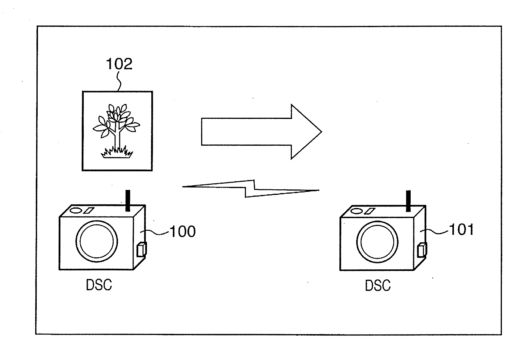
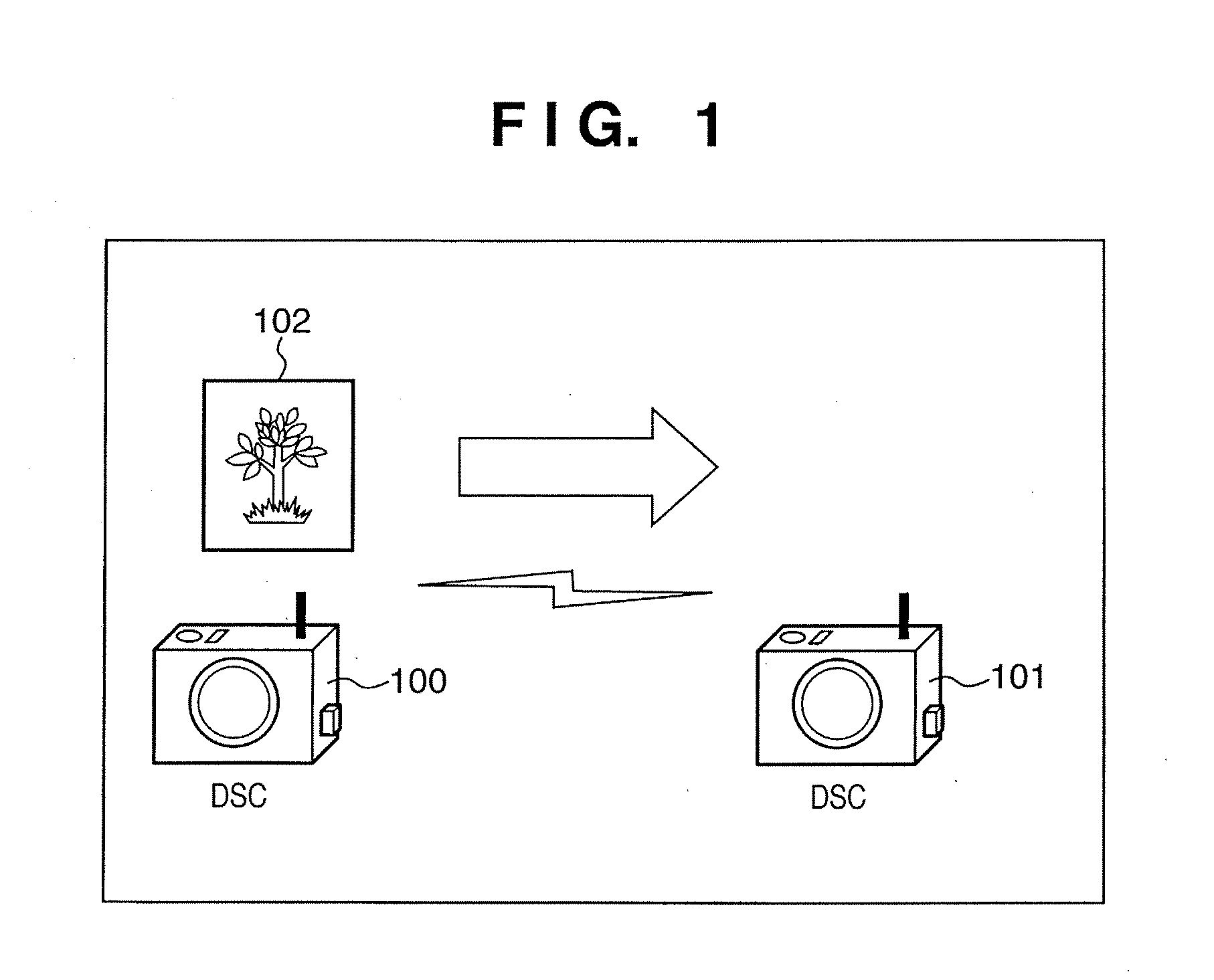
[0024]FIG. 1 is a view showing an example of the configuration of a communication system according to the first embodiment. In this communication system, two digital still cameras (DSCs) serving as communication apparatuses connect to each other in an ad hoc mode of wireless LAN. The DSCs 100 and 101 use PTP (Picture Transfer Protocol) as a communication protocol. In this example, the DSC 100 transmits image data 102 to the DSC 101.

[0025] The hardware configuration of the DSCs 100 and 101 shown in FIG. 1 will be explained. The DSCs 100 and 101 have the same arrangement.

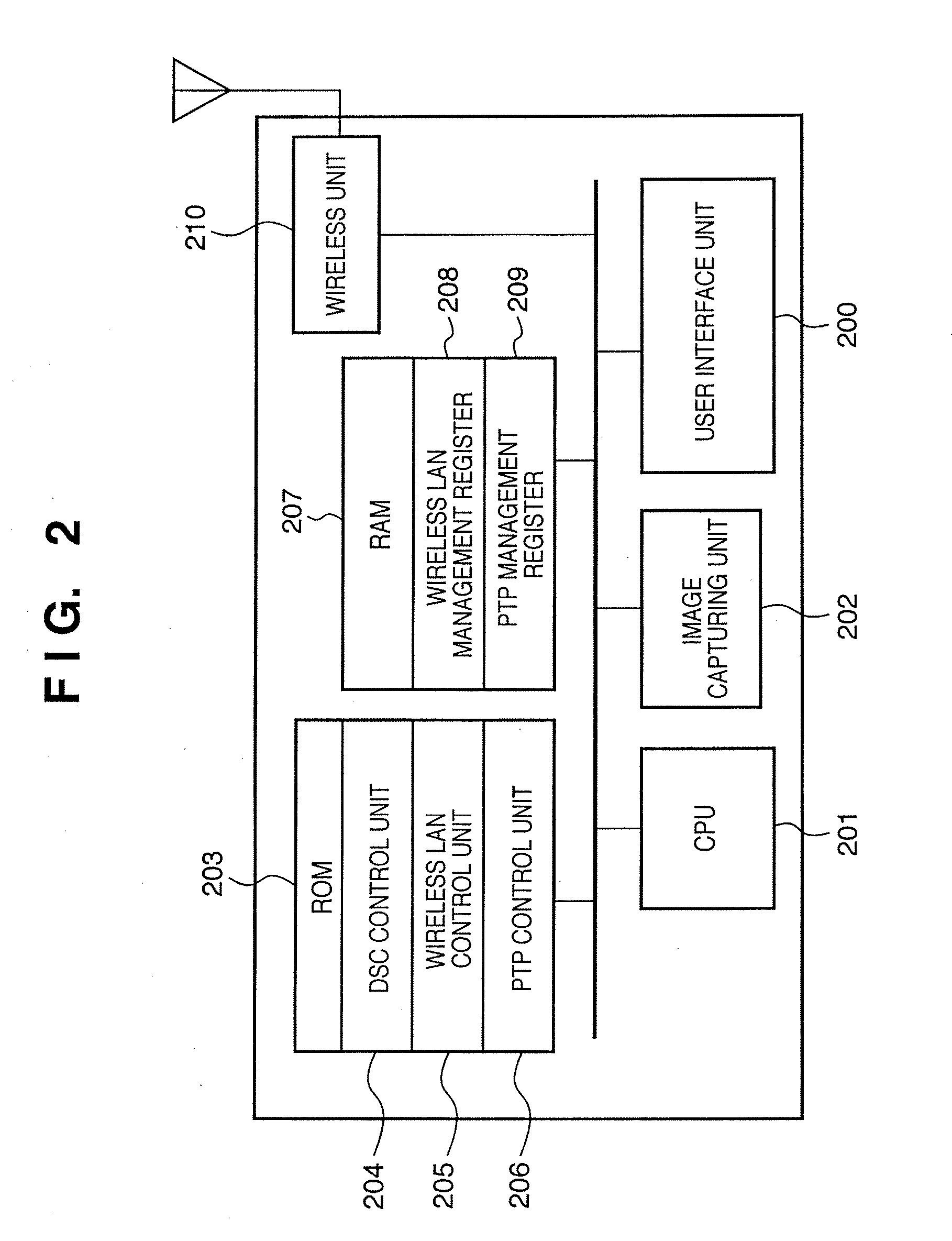
[0026]FIG. 2 is a block diagram showing an example of the arrangement of the digital still camera (DSC). Referring to FIG. 2, a user interface unit 200 including a liquid crystal display screen and keys or a touch panel serves as an interface used by the user to control the DSC. A CPU 201 controls the entire DSC in accordance with programs stored in a ROM to be described later. An image-capturing unit 202 inputs ima...

second embodiment

[0047] The second embodiment of the present invention will be described next in detail with reference to the accompanying drawings. In this embodiment, it is important to fix the transmission power of the communication apparatus on the data-receiving side. In the first embodiment, the “transmission power control function is invalidated” to fix the transmission power of the communication apparatus on the data-receiving side. In the second embodiment, a method of fixing transmission power on the data-receiving side by updating a register to set transmission power will be described.

[0048] The arrangements of the communication system and DSC of the second embodiment are the same as those of the first embodiment described with reference to FIG. 1, and a description thereof will be omitted.

[0049] Transmission power control according to the second embodiment in transmitting image data 102 from a DSC 100 to a DSC 101 will be described with reference to FIGS. 5 to 9.

[0050]FIG. 5 is a view...

third embodiment

[0062] The third embodiment of the present invention will be described next in detail with reference to the accompanying drawings. The first embodiment has been described assuming an ad hoc mode. The same effect is obtained even in an infrastructure mode. The same step numbers as in the first embodiment denote the same processes in the third embodiment, and a detailed description thereof will be omitted.

[0063] Note that known communication control is usable between a communication apparatus and an access point if the network form is the infrastructure mode, and a detailed description thereof will be omitted.

[0064]FIG. 10 is a flowchart showing transmission power control according to the third embodiment. As in the first embodiment, wireless-LAN control units 205 of DSCs 100 and 101 execute wireless connection (S300). It is determined whether the network includes an access point (infrastructure mode) (S1000). If the connection partner is an access point, or the user has instructed ...


PUM


Abstract

In a communication apparatus having a transmission-power control function of controlling transmission power, the operation state of the communication apparatus is determined. If the communication apparatus is determined as a data-transmitting side, control is done to validate the transmission-power control function. If the communication apparatus is determined as a data-receiving side, control is done to invalidate the transmission-power control function.

Description

BACKGROUND OF THE INVENTION [0001] 1. Field of the Invention [0002] The present invention relates to transmission power control of a communication apparatus. [0003] 2. Description of the Related Art [0004] Public radio communications and the like have already implemented transmission power control of battery-driven communication apparatuses and prolonged their driving time. Various schemes have been proposed to control transmission power. For example, patent reference 1: U.S. Pat. No. 6,119,018 (Japanese Patent Laid-Open No. 9-326754) describes a technique of causing a host station to transmit an optimum transmission power control signal to a mobile station. The mobile station subordinately controls its transmission power in accordance with the signal. [0005] PTP (Picture Transfer Protocol) is an image transfer protocol by camera control. A side to request PTP session establishment is called an initiator. The other side to respond to the request is called a responder. After PTP sess...

Claims


Application Information

Patent Timeline
IPC IPC(8): H04B7/00H04Q7/20H04W52/28
CPCH04W52/288Y02B60/50H04W52/283H04W52/28
Inventor SHICHINO, TAKAHIRO
Owner CANON KK
Why Eureka
Try Eureka