Wireless power feeder, wireless power receiver, and wireless power transmission system

a technology of wireless power transmission system and feeder, which is applied in the direction of transformer/inductance circuit, circuit arrangement, inductance, etc., can solve the problem of not being able to feed big electric power, and achieve the effect of effective control of transmission power

Active Publication Date: 2012-02-23
TDK CORPARATION
View PDF4 Cites 35 Cited by
  • Summary
  • Abstract
  • Description
  • Claims
  • Application Information

AI Technical Summary

Benefits of technology

[0042]According to the present invention, it is possible to effectively control transmission power in wireless power feeding of a magnetic field resonance type.

Problems solved by technology

The type (B) utilizing radio wave is available in a long range; however, it cannot feed big electric power.

Method used


Image

  • Wireless power feeder, wireless power receiver, and wireless power transmission system
  • Wireless power feeder, wireless power receiver, and wireless power transmission system
  • Wireless power feeder, wireless power receiver, and wireless power transmission system

Examples


first embodiment

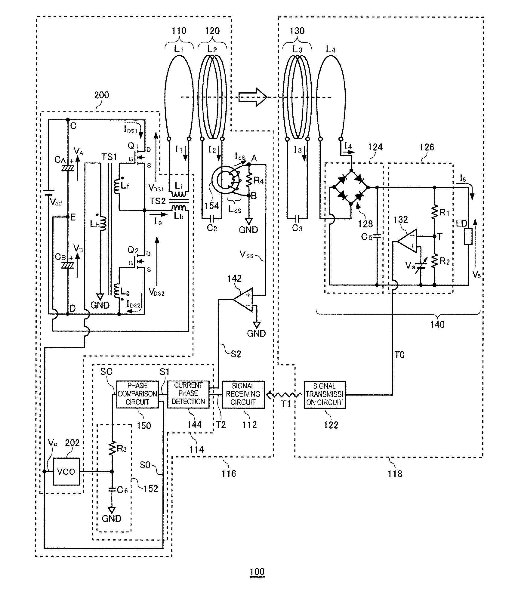
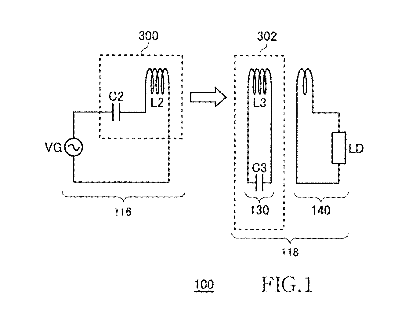
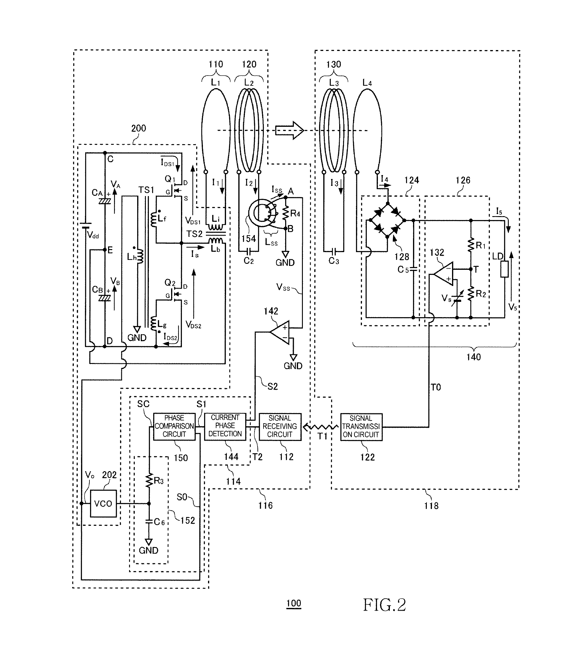
[0080]FIG. 2 is a system configuration view of a wireless power transmission system 100 according to the first and second embodiment. The wireless power transmission system 100 includes a wireless power feeder 116 and a wireless power receiver 118. The wireless power feeder 116 includes, as basic components, a power transmission control circuit 200, an exciting circuit 110, a feeding coil circuit 120, a phase detection circuit 114, and a signal receiving circuit 112. The wireless power receiver 118 includes a receiving coil circuit 130, a loading circuit 140, and a signal transmission circuit 122.

[0081]A distance (hereinafter, referred to as “inter-coil distance”) of about 0.2 m to 1.0 m is provided between a feeding coil L2 of the feeding coil circuit 120 and a receiving coil L3 of the receiving coil circuit 130. The wireless power transmission system 100 mainly aims to feed power from the feeding coil L2 to receiving coil L3 by wireless. In the first embodiment, a description will...

second embodiment

[0144]FIG. 15 is a system configuration view of a wireless power transmission system 1100 according to the second embodiment. The wireless power transmission system 1100 includes a wireless power feeder 1116 and a wireless power receiver 1118. The wireless power feeder 1116 includes, as basic components, a power transmission control circuit 1200, an exciting circuit 1110, a feeding coil circuit 1120, a phase detection circuit 1114, and a signal receiving circuit 1112. The wireless power receiver 1118 includes a receiving coil circuit 1130, a loading circuit 1140, a control signal generation circuit 1170, a reference signal generation circuit 1172, and a signal transmission circuit 1122.

[0145]A distance (hereinafter, referred to as “inter-coil distance”) of about 0.2 m to 1.0 m is provided between a feeding coil L2 of the feeding coil circuit 1120 and a receiving coil L3 of the receiving coil circuit 1130. The wireless power transmission system 1100 mainly aims to feed power from the...

third embodiment

[0224]FIG. 30 is a system configuration view of the wireless power transmission system 100 according to the third embodiment. In the wireless power transmission system 100 of the third embodiment, the capacitor C2 is omitted. Other points are the same as the first embodiment (FIG. 14).


PUM

PropertyMeasurementUnit
distanceaaaaaaaaaa
resonance frequency fr1aaaaaaaaaa
diameteraaaaaaaaaa

Abstract

Power is fed from a feeding coil L2 to a receiving coil L3 by magnetic resonance. A VCO 202 alternately turns ON/OFF switching transistors Q1 and Q2 at a drive frequency fo, whereby AC power is fed to the feeding coil L2, and then the AC power is fed from the feeding coil L2 to the receiving coil L3. A phase detection circuit 114 detects a phase difference between the current phase and voltage phase, and the VCO 202 adjusts the drive frequency fo such that the phase difference becomes zero. When load voltage is changed, the detected current phase value is adjusted with the result that the drive frequency fo is adjusted.

Description

[0001]This is a continuation-in-part of application Ser. No. 12 / 944,566, filed on Nov. 11, 2010.BACKGROUND OF THE INVENTION[0002]1. Field of the Invention[0003]The present invention relates to a wireless AC power feeding and, more particularly, to power control thereof.[0004]2. Description of Related Art[0005]A wireless power feeding technique of feeding power without a power cord is now attracting attention. The current wireless power feeding technique is roughly divided into three: (A) type utilizing electromagnetic induction (for short range); (B) type utilizing radio wave (for long range); and (C) type utilizing resonance phenomenon of magnetic field (for intermediate range).[0006]The type (A) utilizing electromagnetic induction has generally been employed in familiar home appliances such as an electric shaver; however, it can be effective only in a short range of several centimeters. The type (B) utilizing radio wave is available in a long range; however, it cannot feed big ele...

Claims


Application Information

Patent Timeline
Patent Type & Authority Applications(United States)
IPC IPC(8): H01F38/00
CPCH02J17/00H02J5/005H02J50/12
Inventor URANO, TAKASHI
Owner TDK CORPARATION
Why Eureka
Try Eureka