System and method of an adjustable bed with a vibration motor

a technology of vibration motor and adjustable bed, which is applied in the field of adjustable beds, can solve the problems of significant amount of time in the bed, and achieve the effect of improving the comfort of patients

Active Publication Date: 2016-05-05
RAWLS MEEHAN MARTIN B
View PDF2 Cites 58 Cited by
  • Summary
  • Abstract
  • Description
  • Claims
  • Application Information

AI Technical Summary

Problems solved by technology

These users, whether at home or in a medical environment such as a hospital, nursing home, assisted living facility, or long-term care facility, may, because of these issues, spend significant amounts of time in bed, and some users may be confined to spending long periods of time in or on furniture.

Method used


Image

  • System and method of an adjustable bed with a vibration motor
  • System and method of an adjustable bed with a vibration motor
  • System and method of an adjustable bed with a vibration motor

Examples


Embodiment Construction

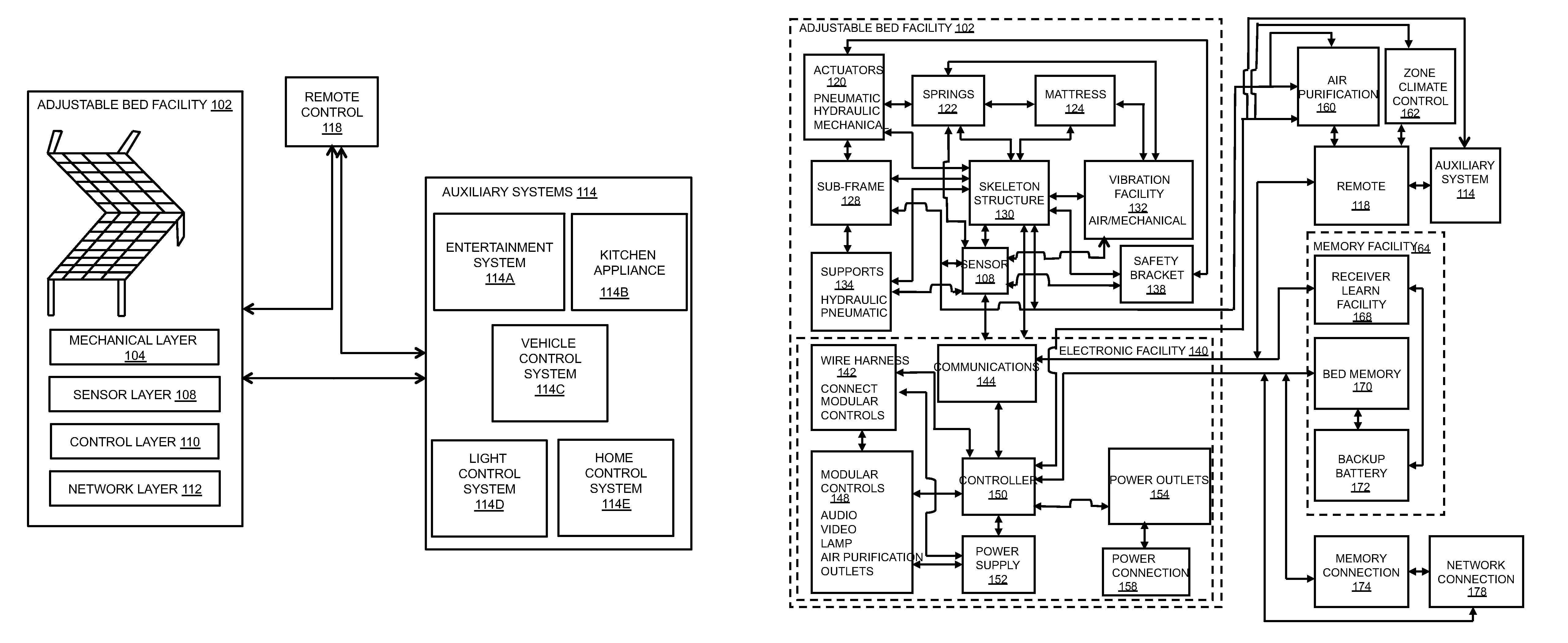
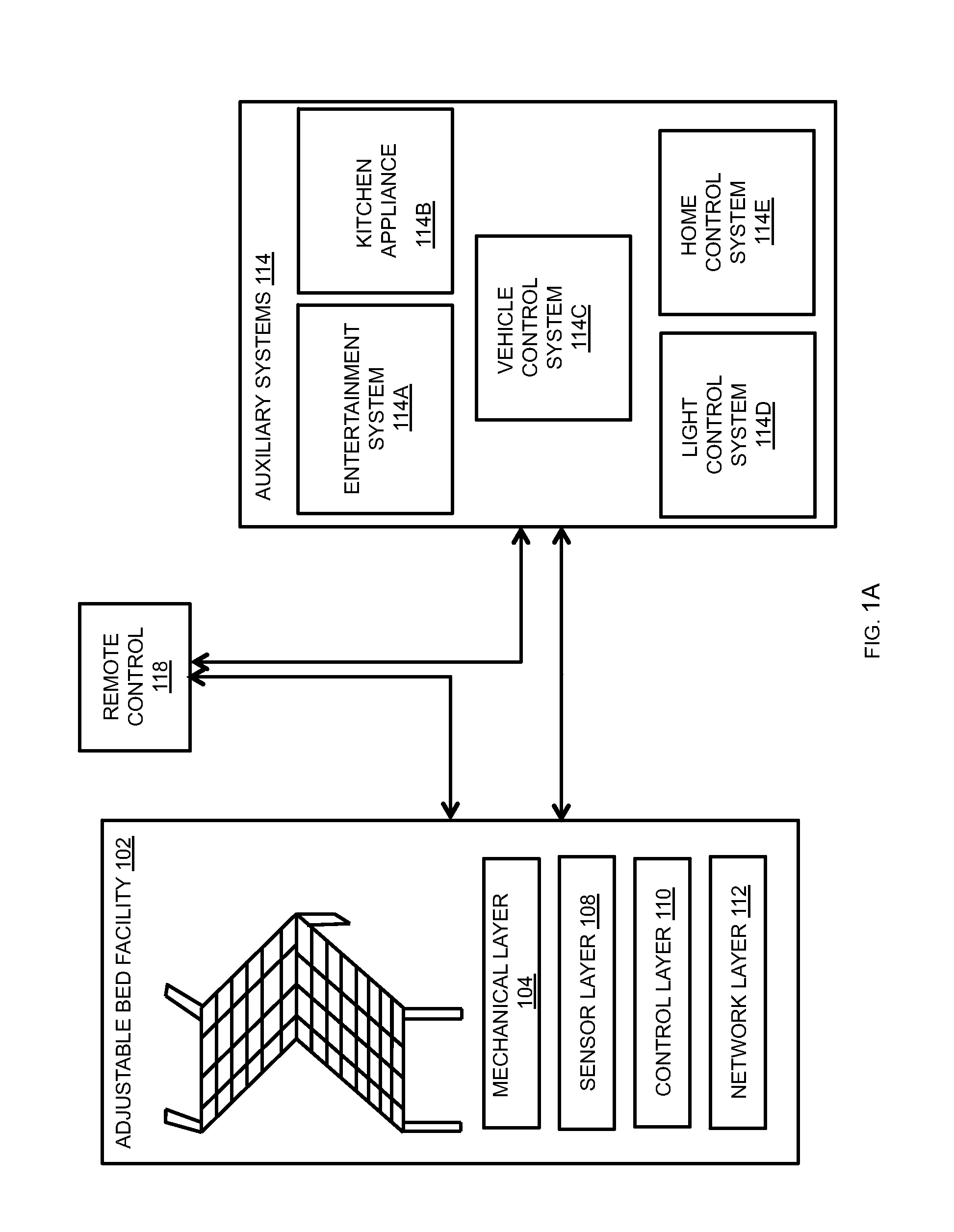
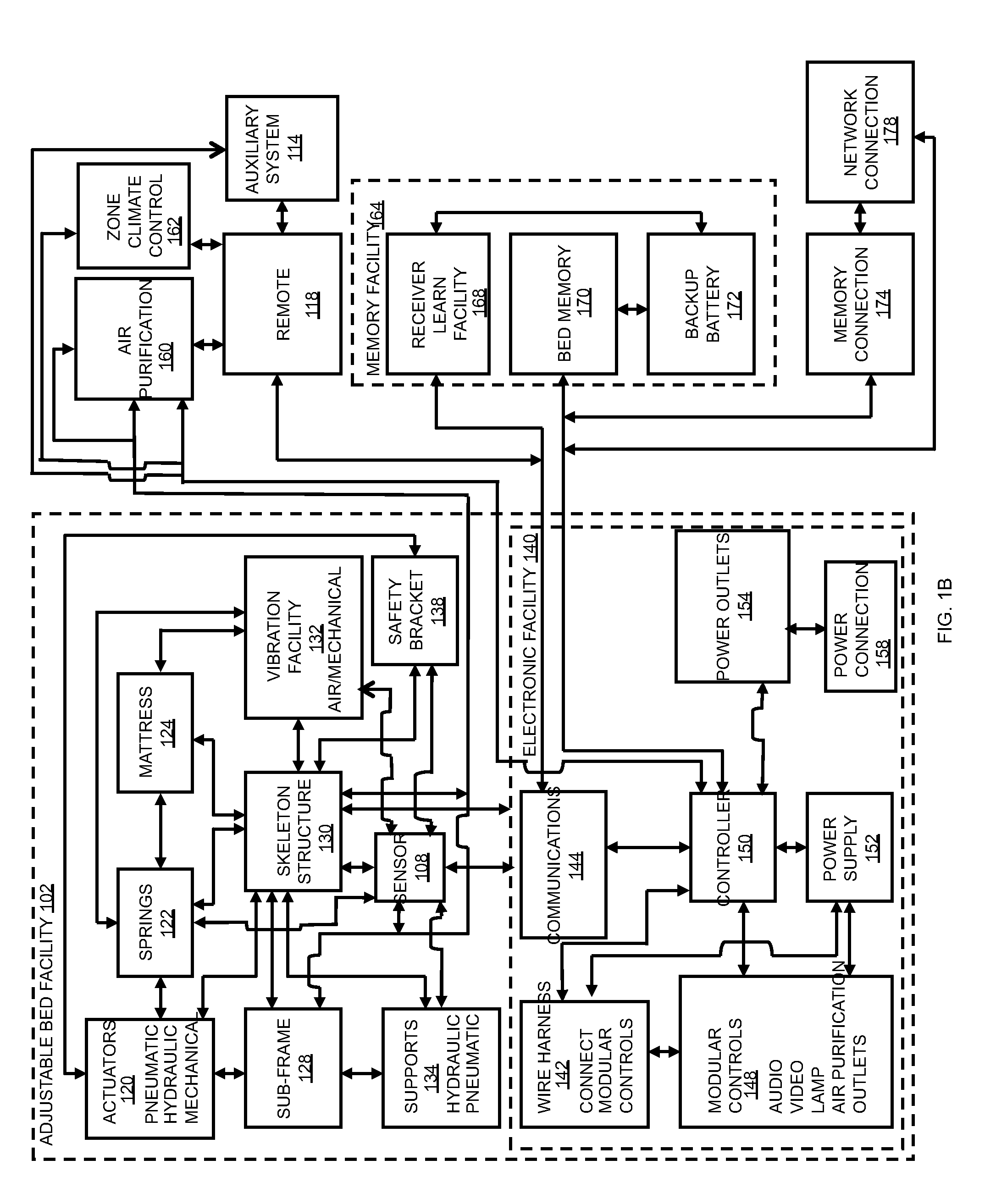
[0186]In the following description, terms such as ‘adjustable mattress’, ‘adjustable bed’, ‘adjustable bed facility’ and the like are used interchangeably to refer generally to an apparatus including a sleeping or resting surface with one or more adjustable or moveable sub-surfaces that can be positioned for user comfort and / or convenience, unless a specific meaning is explicitly provided or otherwise clear from the context.

[0187]As users spend more and more time in adjustable beds they may desire to have a level of independence by controlling devices that may be in the room from the adjustable bed. The devices and facilities that users may wish to control may include audio equipment, video equipment, lamps, air purification facilities, power outlets, and the like. It may be desirable for the user to control these devices and facilities from the adjustable bed without having to leave the bed or ask for aid from someone else. For example, the user may be confined to the bed and may w...


PUM


Abstract

The present disclosure concerns an adjustable bed facility including a system for executing a computer-based safety-action during a motor-actuated adjustable bed position adjustment, comprising an adjustable bed facility comprising a computer-based controller, an actuator, and a sensor, the computer-based controller providing control of adjustable bed position adjustments, the actuator configured to adjust a height of the adjustable bed facility upon receiving a height-adjustment command from the computer-based controller, and the sensor for determining an actuator action parameter measured value of the actuator, the computer-based controller in communicative connection with the sensor to monitor and compare the motor action parameter measured value to an actuator action parameter normal operation value range, and when the controller determines the monitored motor action parameter measured value is outside the range of the actuator action parameter normal operation value range the controller sends a safety-action command to the actuator.

Description

CROSS-REFERENCE TO RELATED APPLICATIONS[0001]This application claims the benefit of the following provisional applications, each of which is hereby incorporated by reference in its entirety:[0002]U.S. Provisional Patent Application Ser. No. 61 / 648,985, filed May 18, 2012 (Docket No. REVE-0016-P60); U.S. Provisional Patent Application Ser. No. 61 / 764,963, filed Feb. 14, 2013 (Docket No. REVE-0018-P60); and U.S. Provisional Patent Application Ser. No. 61 / 765,796, filed Feb. 17, 2013 (Docket No. REVE-0020-P60).[0003]This application is a continuation-in-part of U.S. patent application Ser. No. 13 / 286,812, filed Nov. 1, 2011 (Docket No. REVE-0015-P01), which is hereby incorporated by reference in their entirety and which claims priority to U.S. Provisional Patent Application Ser. No. 61 / 408,778, filed Nov. 1, 2010 (Docket No. REVE-0014-P60) and U.S. Provisional Patent Application Ser. No. 61 / 508,958, filed Jul. 18, 2011 (Docket No. REVE-0015-P60), all of which are hereby incorporated by...

Claims


Application Information

Patent Timeline
Patent Type & Authority Applications(United States)
IPC IPC(8): A61H23/02A61G7/015
CPCA61H23/0263A61H2203/0443A61H2201/0142A61G7/015
Inventor RAWLS-MEEHAN, MARTIN B.
Owner RAWLS MEEHAN MARTIN B
Why Eureka
Try Eureka