
Bearing component with composite flange

Active Publication Date: 2016-05-05
AB SKF
View PDF5 Cites 0 Cited by
  • Summary
  • Abstract
  • Description
  • Claims
  • Application Information

AI Technical Summary

Benefits of technology

The invention is a method of manufacturing a flanged bearing ring that is strong and stiff enough to withstand substantial forces. The method involves introducing forces through the connection interfaces between the flange part and the ring part, which results in a reaction force on the other interface. This load path is in alignment with the fiber-reinforcement in the flange part, making it stronger and stiffer than other parts of the bearing. The manufacturing method is robust and can produce a lightweight flanged bearing ring.

Problems solved by technology

They are also expensive and, consequently, bearing steel is more commonly used.
Bearing steel has excellent hardenability but cannot be viewed as a lightweight material.

Method used


Image

  • Bearing component with composite flange
  • Bearing component with composite flange
  • Bearing component with composite flange

Examples


Embodiment Construction

[0031]A hub bearing unit is an example of a bearing that may comprise at least one flanged bearing ring. In some examples, the inner ring of the hub bearing unit has a wheel mounting flange for mounting a wheel rim and a brake disc to the bearing. The outer ring may also comprise a flange for attaching the bearing to e.g. a steering knuckle. In other examples, adapted for outer ring rotation, the bearing outer ring comprises a wheel mounting flange.

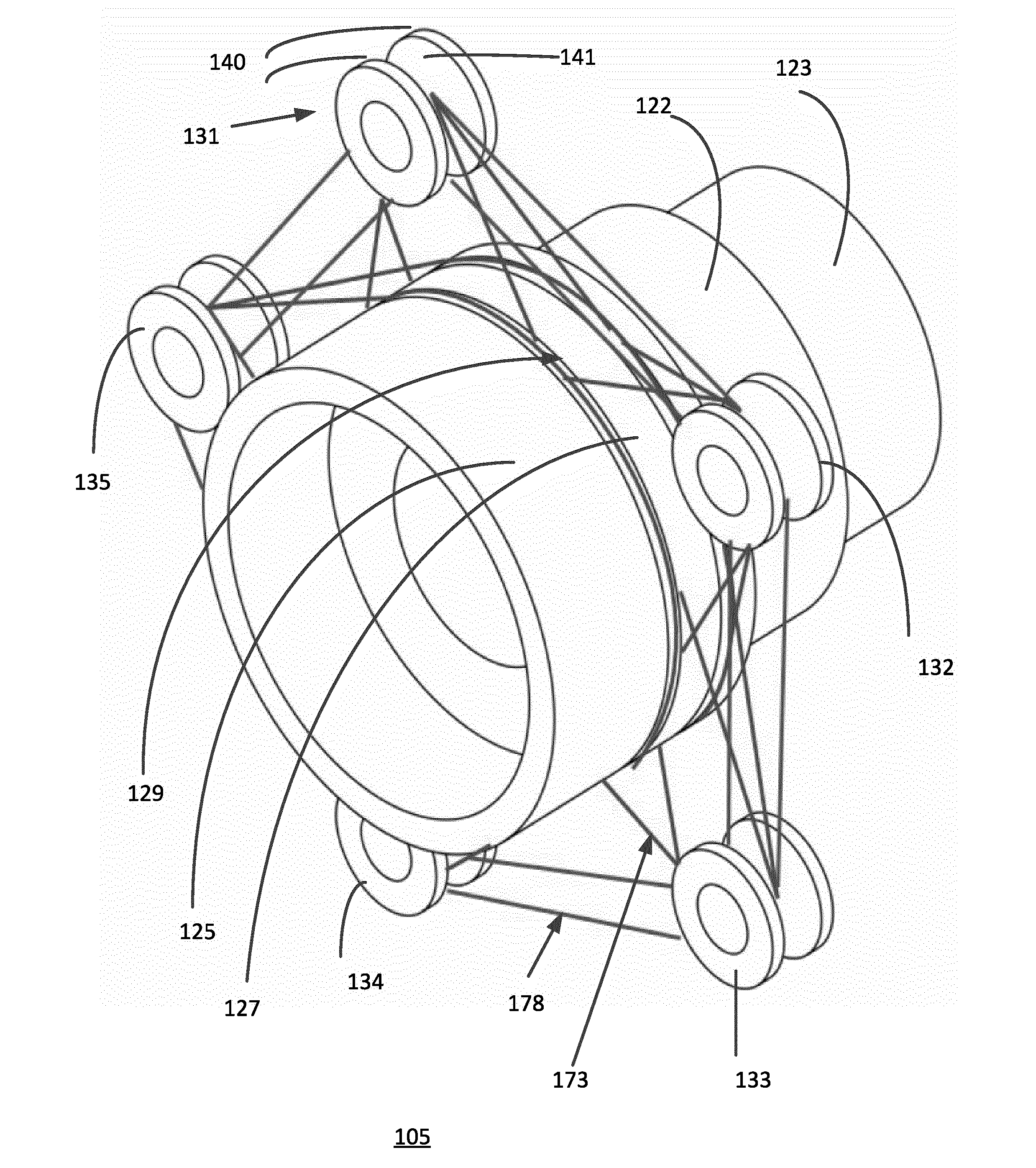
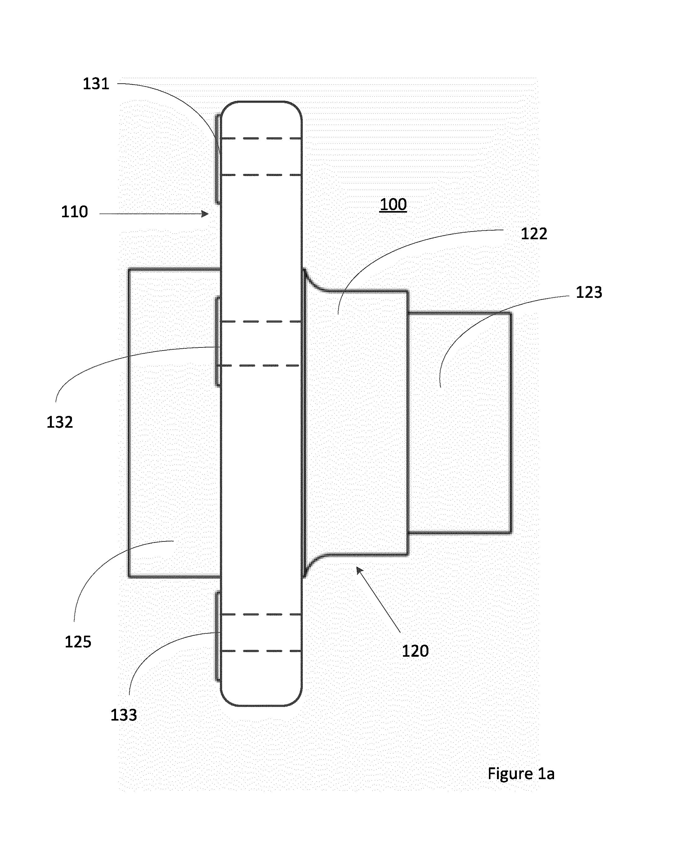
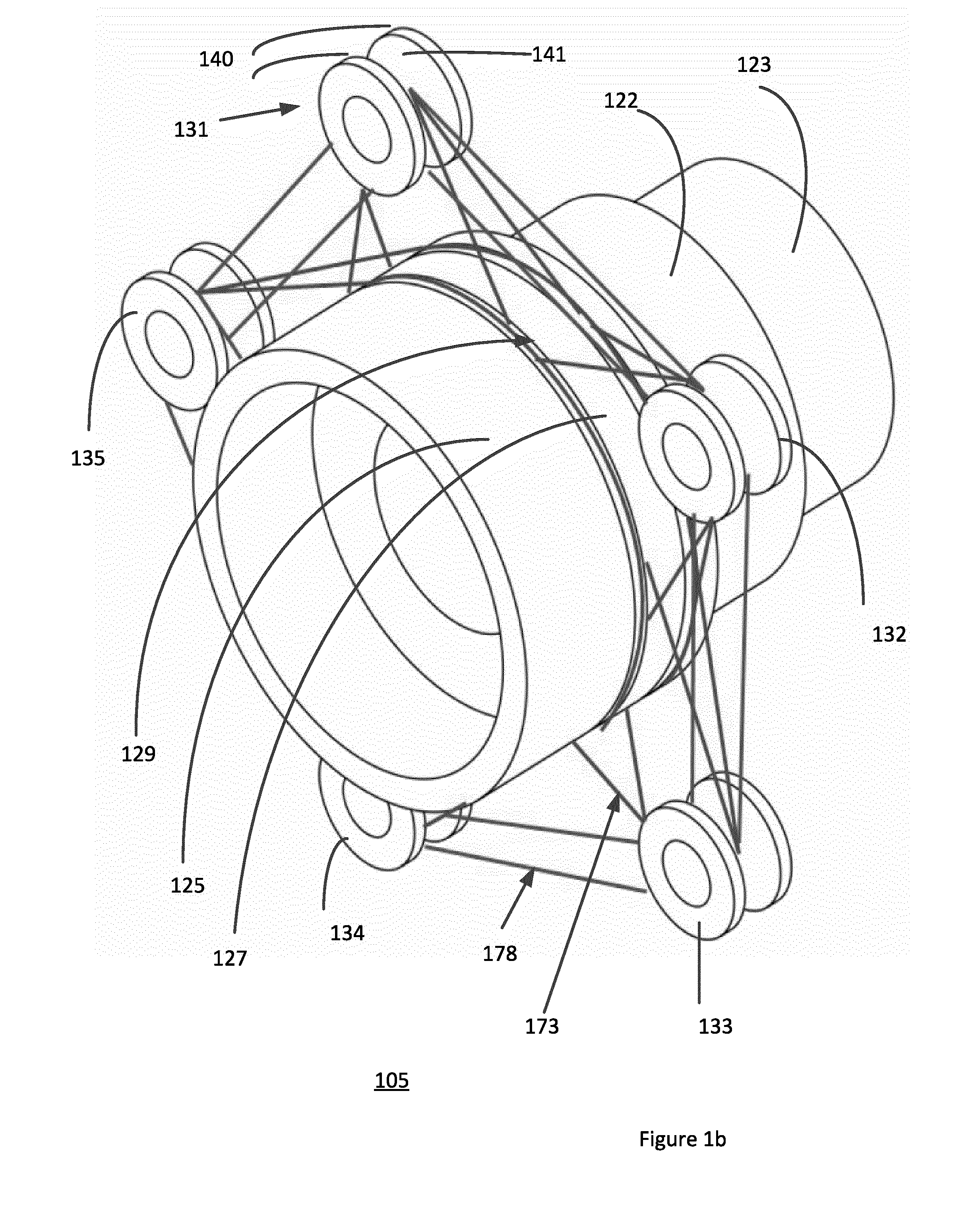
[0032]An example of a flanged bearing ring according to the invention is depicted in FIG. 1a. The flanged bearing ring 100 will form part of a hub bearing unit adapted for inner ring rotation, and comprises a radially extending wheel mounting flange 110 and an axially extending inner ring part 120. The ring part is made of bearing steel in the depicted example and comprises a raceway portion 122 with a hardened surface for receiving a row of rolling elements. The bearing will further comprise a separate inner ring (not shown) that is moun...


PUM

PropertyMeasurementUnit
Diameteraaaaaaaaaa
Widthaaaaaaaaaa
Depthaaaaaaaaaa

Abstract

A flanged bearing ring comprising a flange part joined to a ring part. The flange part is at least partly made of a fiber-reinforced matrix material, which is overmolded to the ring part. The flange part further comprises a first connection interface for enabling a component such as a vehicle wheel to be screwed or bolted to the flange part. The first connection interface comprises a plurality of bolt inserts which are embedded in the fiber-reinforced matrix material. At least one bolt insert is joined to the ring part by a continuous fiber tow that is wound around part of an outer surface of the bolt insert and of the ring part. Suitably, each bolt insert is joined to the ring part in this manner.

Description

CROSS REFERENCE TO RELATED APPLICATIONS[0001]This is a United States National Stage Application claiming the benefit of International Application Number PCT / EP2014 / 061886 filed on 6 Jun. 2014 (06.06.2014), which claims the benefit of Europe (EP) Patent Application PCT / EP2013 / 061790 filed on 7 Jun. 2013 (07.06.2013), both of which are incorporated herein by reference in their entireties.FIELD OF THE INVENTION[0002]The present invention relates to a flanged bearing ring, especially a flanged bearing ring of a hub bearing unit, which has a flange part that is at least partly made from a fiber-reinforced composite.BACKGROUND TO THE INVENTION[0003]In the interests of fuel economy, there is an increasing drive within the automotive industry towards weight reduction of the component parts of vehicles. A vehicle wheel bearing is one example of an automotive component where weight reduction is desirable, also in view of the fact that the wheel bearings belong to the unsprung weight of a vehi...

Claims


Application Information

Patent Timeline
IPC IPC(8): B60B27/06B60B5/02B60B27/00
CPCB60B27/065B60B5/02B60B27/0094B60B27/00B60B2310/321B60B2900/111B60G2206/50B60G2206/71Y02T10/86F16C35/06F16C19/186F16C33/581F16C33/586F16C2326/02B62D7/18B29C70/845B29K2263/00B29K2307/04
Inventor PETERS, GILBERTSCHAAKE, RICHARDSCHRAMM, EDOVISSERS, CORNELIUS PETRUS ANTONIUS
Owner AB SKF
Learn More