
Threaded sleeve

a threaded sleeve and threaded technology, applied in the direction of threaded fasteners, screws, fastening means, etc., can solve the problems of insufficient tensile strength of the connection between the threaded sleeve and the workpiece, the external thread has not anchored itself deep enough into the surrounding workpiece, etc., to facilitate the screwing-in process

Active Publication Date: 2016-05-05
RAMPA GMBH & CO KG
View PDF0 Cites 1 Cited by
  • Summary
  • Abstract
  • Description
  • Claims
  • Application Information

AI Technical Summary

Benefits of technology

The purpose of this invention is to create a threaded sleeve that makes it easier to screw in and ensures a secure and loadable connection between the sleeve and the material after screwing. This results in a more efficient and effective assembly process.

Problems solved by technology

It has proved to be a disadvantage of the known threaded sleeves that when screwing the threaded sleeve into a workpiece said threaded sleeve tilts and the threaded sleeve is assembled askew.
For this reason, the necessary predrilled hole is often embodied larger which results in that insufficient tensile strength of the connection between threaded sleeve and workpiece can be established.
The reason for this is that upon successful assembly of the threaded sleeve the external thread has not anchored itself deep enough into the surrounding workpiece.
Upon askew assembly of the threaded sleeve in the workpiece, crack formations, heating of the workpiece or its deformation frequently occur.
Furthermore, asymmetrical stress distribution and loads in the workpiece can result in the fracture or destruction of the same.

Method used


Image

  • Threaded sleeve
  • Threaded sleeve
  • Threaded sleeve

Examples


Embodiment Construction

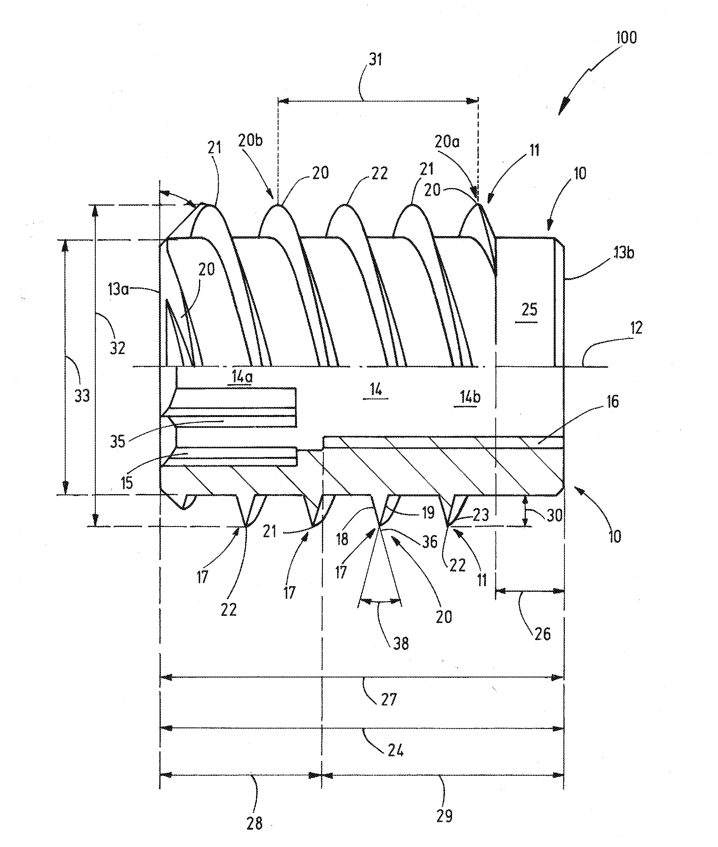
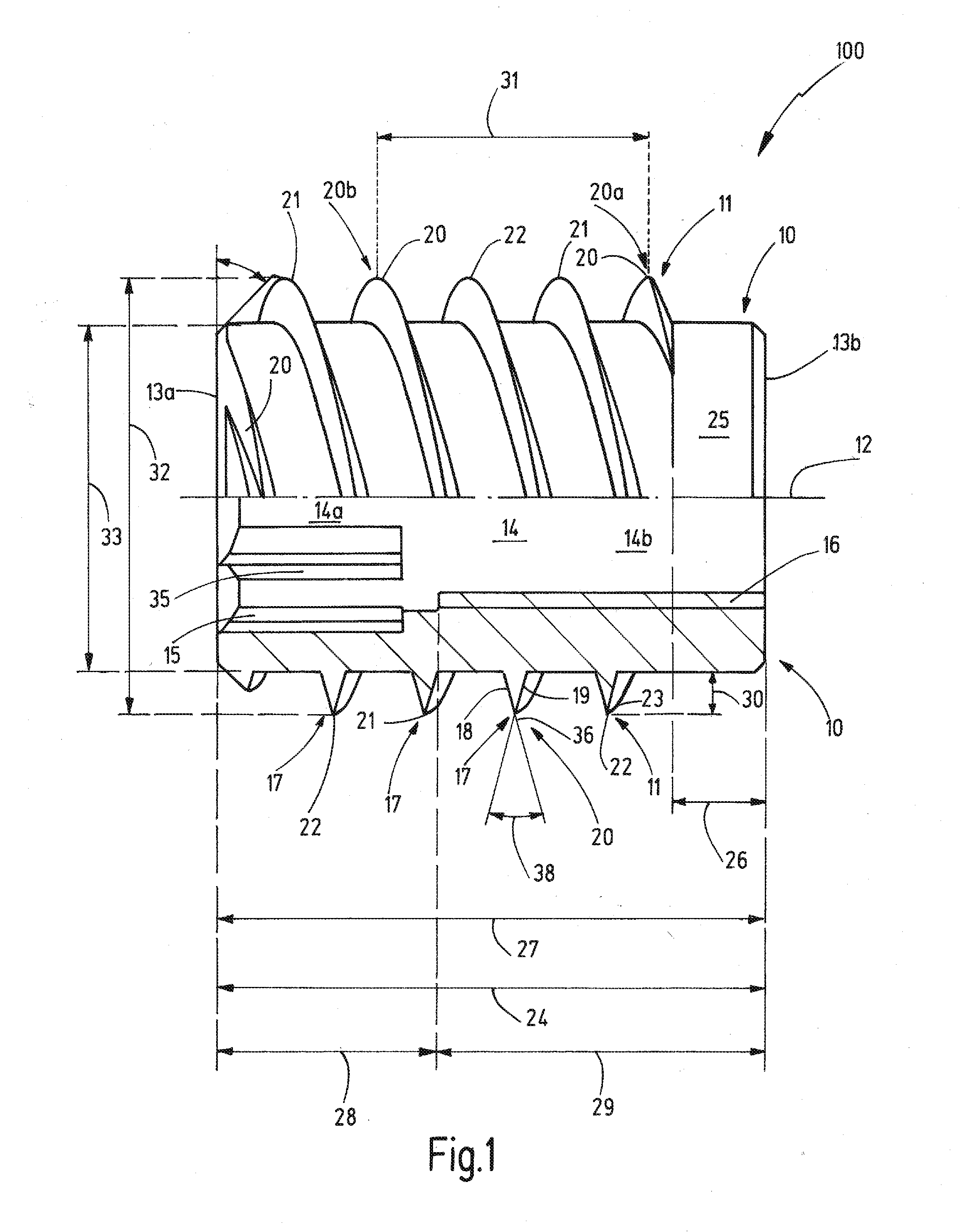
[0042]FIG. 1 shows a lateral view and a longitudinal section of a threaded sleeve 100 according to the invention of length 24 comprising a cylindrical core 10 and a thread 11 that is mounted outside on the core 10. The lower half of FIG. 1 shows a section along the longitudinal axis 12 of the threaded sleeve 100, while on the upper half a lateral view of the threaded sleeve 100 is visible.

[0043]The thread 11 of the threaded sleeve 100 is of the triple-threaded design and thus comprises three thread turns 20, 21, 22. In the upper figure half it is evident how the three thread turns 20, 21, 22 of the triple-threaded thread 11 helically wind about the core 10 from the one end 13b to the other end 13a of the threaded sleeve 100. Here, a region 25, the so-called guiding tip, is formed without threads along the length 26 at the end 13b of the threaded sleeve 100. This threadless region 25 along the length 26 serves for the perpendicularly guided insertion of the threaded sleeve 100 into a...


PUM


Abstract

The invention relates to a threaded sleeve for screwing into a receiving opening of a workpiece, with a core and a thread mounted outside on the core, wherein the thread has three thread turns, wherein the thread turns have a thread profile, wherein the thread profile has a flank angle of 25° to 35°, wherein with an outer diameter of 8 mm to 14 mm the pitch of the thread is in the range of 0.5 to 1.0 times the outer diameter of the threaded sleeve and with an outer diameter greater than 14 mm to 40 mm, pitch of the thread is in the range of 0.25 to 0.65 times the outer diameter of the threaded sleeve, and wherein the thread depth of the thread profile is in the range of 0.03 times to 0.15 times the outer diameter of the threaded sleeve.

Description

FIELD OF INVENTION[0001]The invention relates to a threaded sleeve for screwing into a receiving opening of a workpiece.BACKGROUND OF THE INVENTION[0002]Threaded sleeves with a core and a thread attached on the outside of the same are known from the prior art. It has proved to be a disadvantage of the known threaded sleeves that when screwing the threaded sleeve into a workpiece said threaded sleeve tilts and the threaded sleeve is assembled askew. For this reason, the necessary predrilled hole is often embodied larger which results in that insufficient tensile strength of the connection between threaded sleeve and workpiece can be established. The reason for this is that upon successful assembly of the threaded sleeve the external thread has not anchored itself deep enough into the surrounding workpiece.[0003]Upon askew assembly of the threaded sleeve in the workpiece, crack formations, heating of the workpiece or its deformation frequently occur. Furthermore, asymmetrical stress d...

Claims


Application Information

Patent Timeline
Patent Type & Authority Applications(United States)
IPC IPC(8): F16B35/00F16B33/02
CPCF16B33/02F16B35/00F16B37/127F16B25/0068
Inventor FARBER, WOLFGANG
Owner RAMPA GMBH & CO KG
Learn More