Electric arc furnace

a technology of electric arc furnace and arc furnace shell, which is applied in the direction of electric heating for furnaces, furnace types, furnaces, etc., can solve the problems of affecting the smooth movement affecting the accuracy of the furnace shell, so as to prevent damage and high accuracy

Active Publication Date: 2016-05-05
DAIDO STEEL CO LTD
View PDF2 Cites 3 Cited by
  • Summary
  • Abstract
  • Description
  • Claims
  • Application Information

AI Technical Summary

Benefits of technology

[0018]In the electric arc furnace according to the present invention, an insulation member (first insulation member) is provided between the furnace shell and the furnace shell moving mechanism. Therefore, even in a case where current flows in the furnace shell due to current flowing in an electrode, the current flowing in the furnace shell is prevented from flowing in the furnace shell moving mechanism from the furnace shell. As a result, the furnace shell moving mechanism is prevented from being damaged by the current.
[0019]Here, in the case where the furnace shell moving mechanism includes a first part that is fixed with respect to the installation surface and a second part that is fixed to the furnace shell and is movable with respect to the first part and the first part is electrically connected to the second part, the first part and the second part become equipotential. Thus, even if current flows in the furnace shell moving mechanism due to dielectric breakdown or the like of the first insulation member which electrically insulates between the furnace shell and the furnace shell moving mechanism, such a phenomenon unlikely occurs that current flows over a wide area within the furnace shell moving mechanism. As a result, the furnace shell moving mechanism can be prevented with high accuracy from being damaged seriously.
[0020]In this case, if a connecting wire for electrically connecting between the first part and the second part of the furnace shell moving mechanism is provided and has a length capable of following the entire movable range of the second part, the connecting wire is prevented from being damaged and applied with an excessive force even when the second part is moved with respect to the first part.
[0021]Further, in the case where the furnace shell and the furnace shell moving mechanism are independently grounded, the current flowing in the furnace shell can be more firmly prevented from flowing in the furnace shell moving mechanism.
[0022]Furthermore, in the case where the electric arc furnace further includes a furnace roof that covers the opening of the furnace shell, a furnace roof moving mechanism that moves the furnace roof with respect to the furnace shell, and an second insulation member that electrically insulates between the furnace roof moving mechanism and the furnace shell, the current flowing in the furnace shell can also be prevented from flowing in the furnace roof moving mechanism. Accordingly, a member constituting the furnace roof moving mechanism can also be prevented from being damaged due to the current.
[0023]In this case, if the furnace shell and the furnace roof moving mechanism are independently grounded, the current flowing in the furnace shell can be more firmly prevented from flowing in the furnace roof moving mechanism.

Problems solved by technology

If a leak current flowing through the metal material within the furnace shell or the induction current flowing through the surface of the furnace shell flows in this kind of movable part, such the current may damage the movable part and impair a function of the movable part.
For example, in a state that an electrode are inserted into the furnace shell and supplied with current, if a leak current flowing through the metal material within the furnace shell or an induction current generated in the furnace shell flows in a member such as the bearing of the furnace shell moving mechanism and generates spark, even when the furnace shell moving mechanism is in a static state, constitutional members of the furnace shell moving mechanism may be damaged, and hence succeeding smooth movement of the furnace shell may be interfered.

Method used


Image

  • Electric arc furnace
  • Electric arc furnace
  • Electric arc furnace

Examples


Embodiment Construction

[0028]Explanation will be made with reference to the drawings as to an electric arc furnace according to an embodiment of the present invention.

(Configuration of Electric Arc Furnace)

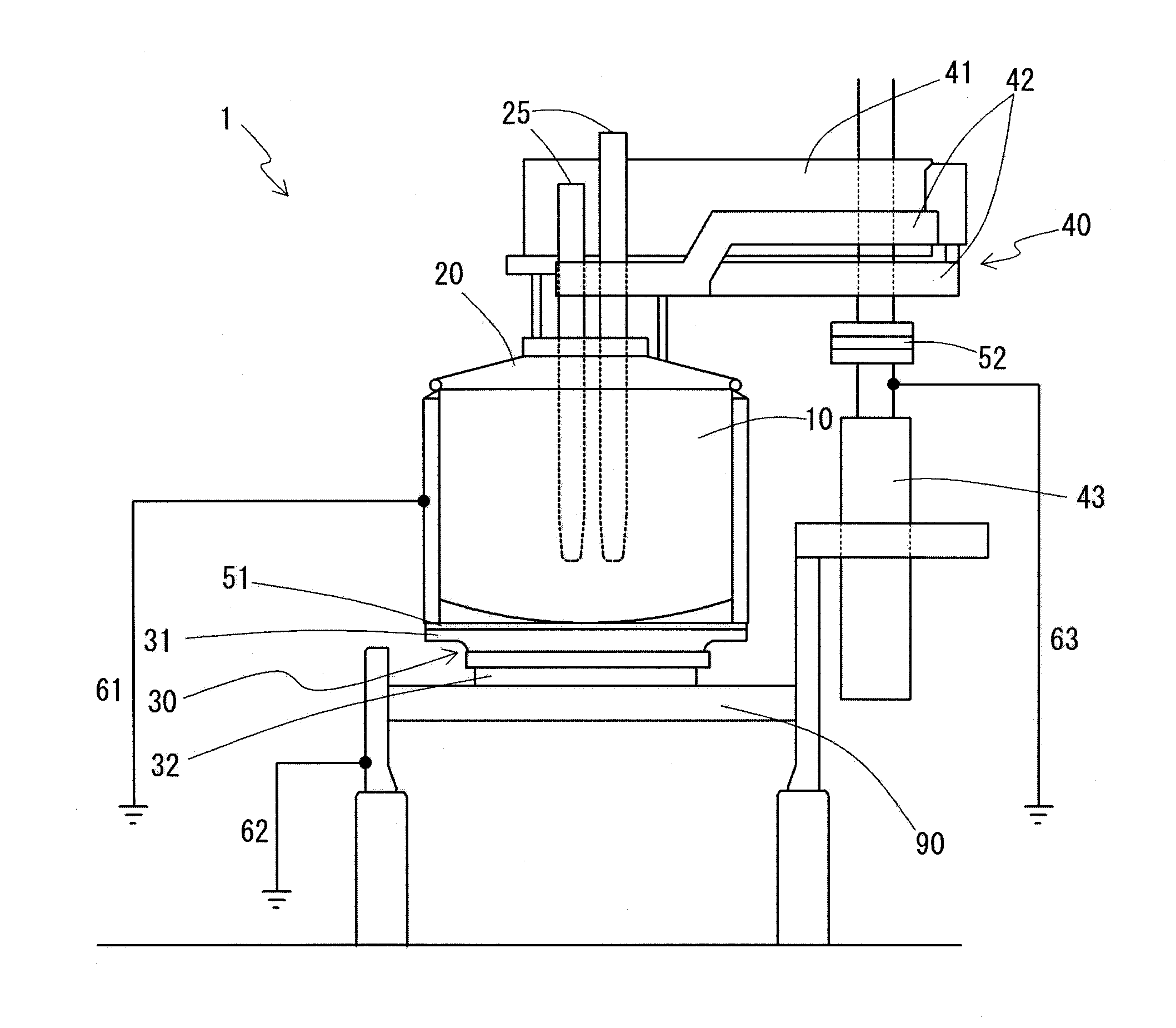
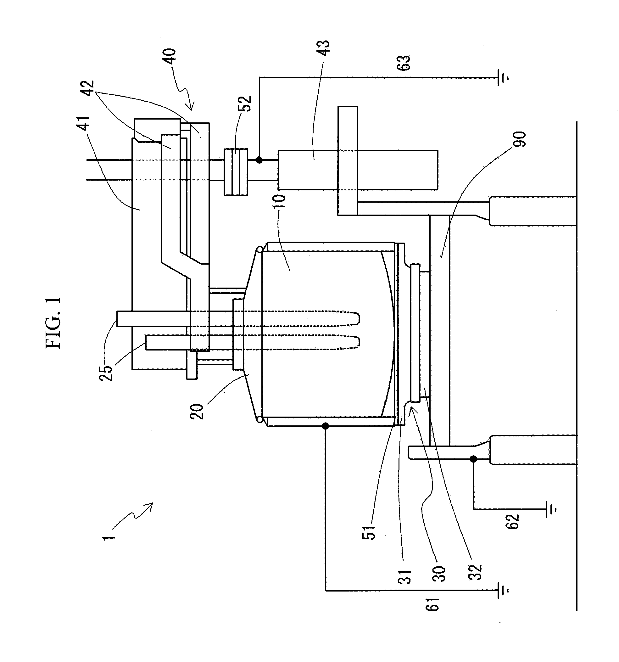
[0029]FIG. 1 to FIG. 4B illustrate an electric arc furnace 1 according the embodiment of the present invention. The electric arc furnace 1 is installed on a platform 90. The electric arc furnace 1 has, as a main body part, an electric arc furnace (arc furnace) similar to that described in Patent Literature 1, and includes a furnace shell 10, a furnace roof 20 and electrodes 25. In addition, the electric arc furnace 1 includes a furnace shell moving mechanism 30 and a furnace roof holding unit 40 having a furnace roof moving mechanism 43. Further, the electric arc furnace 1 also includes a furnace shell insulation member (first insulation member) 51 and a furnace roof insulation member (second insulation member) 52 as insulation members, and a furnace shell ground wire 61, a furnace shell moving mechanis...


PUM

PropertyMeasurementUnit
rotatable angleaaaaaaaaaa
currentaaaaaaaaaa
induction currentaaaaaaaaaa

Abstract

The present invention relates to an electric arc furnace, containing a furnace shell, an electrode, a furnace shell moving mechanism that supports the furnace shell so as to be movable on an installation surface, and a first insulation that electrically insulates between the furnace shell and the furnace shell moving mechanism.

Description

FIELD OF THE INVENTION[0001]The present invention relates to an electric arc furnace and, in particular, relates to an electric arc furnace in which metal is melted while moving a furnace shell.BACKGROUND ART OF THE INVENTION[0002]In an arc furnace as a kind of electric arc furnace for melting metal material, a so-called hot spot and cold spot are formed within an inner space of a furnace shell containing the metal material. The hot spot places close to electrodes and at which the metal material is likely to be melted. The cold spot places distant from the electrodes and at which the metal material is not likely to be melted. In the cold spot, there arise a problem that it takes a long period of time to melt the metal material and thus melting of the metal material proceeds uniformly as a whole. In order to solve this problem, Patent Literature 1 proposes a process in which a furnace shell is rotationally displaced around an axis line extending in an up-down direction with respect t...

Claims


Application Information

Patent Timeline
Patent Type & Authority Applications(United States)
IPC IPC(8): F27B14/06F27B14/12F27D11/08
CPCF27B14/06F27D11/08F27B2014/0831F27B2014/0825F27B14/12F27B3/085F27B3/12
Inventor MIZUTANI, KOTAOGAWA, MASATOMATSUO, KUNIO
Owner DAIDO STEEL CO LTD
Why Eureka
Try Eureka