
Method, computer program, and system for adjusting cameras

a technology of camera and computer program, applied in the field of computer program and system for adjusting cameras, can solve the problems of time-consuming and laborious process, add to the difficulty of focusing the security camera, and time-consuming methods

Inactive Publication Date: 2016-05-05
WOW INSITES
View PDF6 Cites 7 Cited by
  • Summary
  • Abstract
  • Description
  • Claims
  • Application Information

AI Technical Summary

Benefits of technology

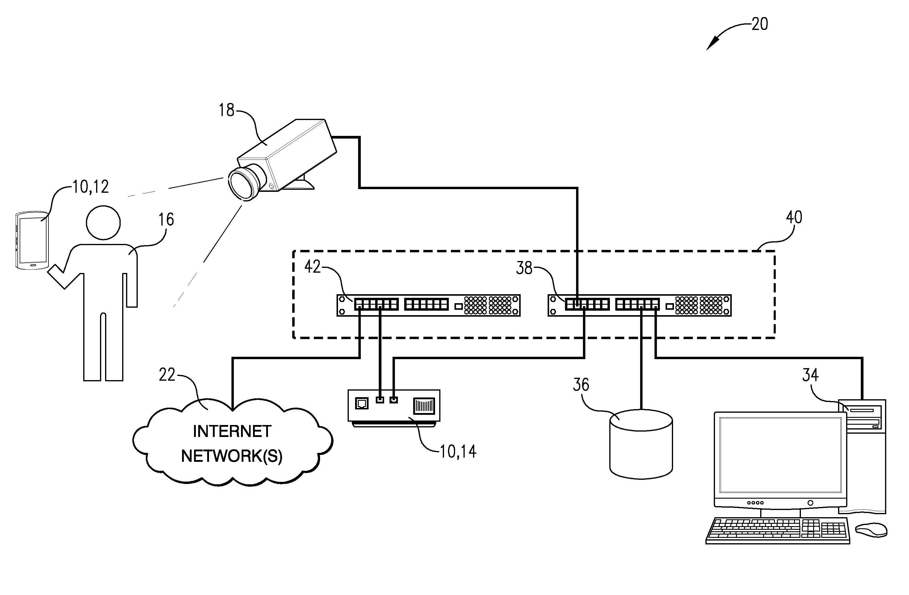
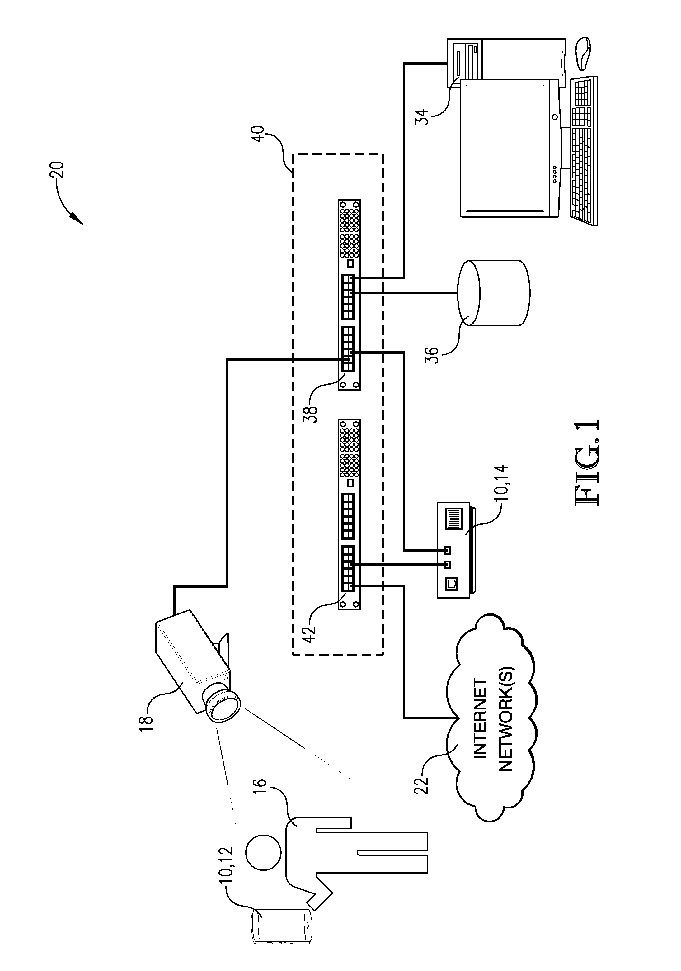
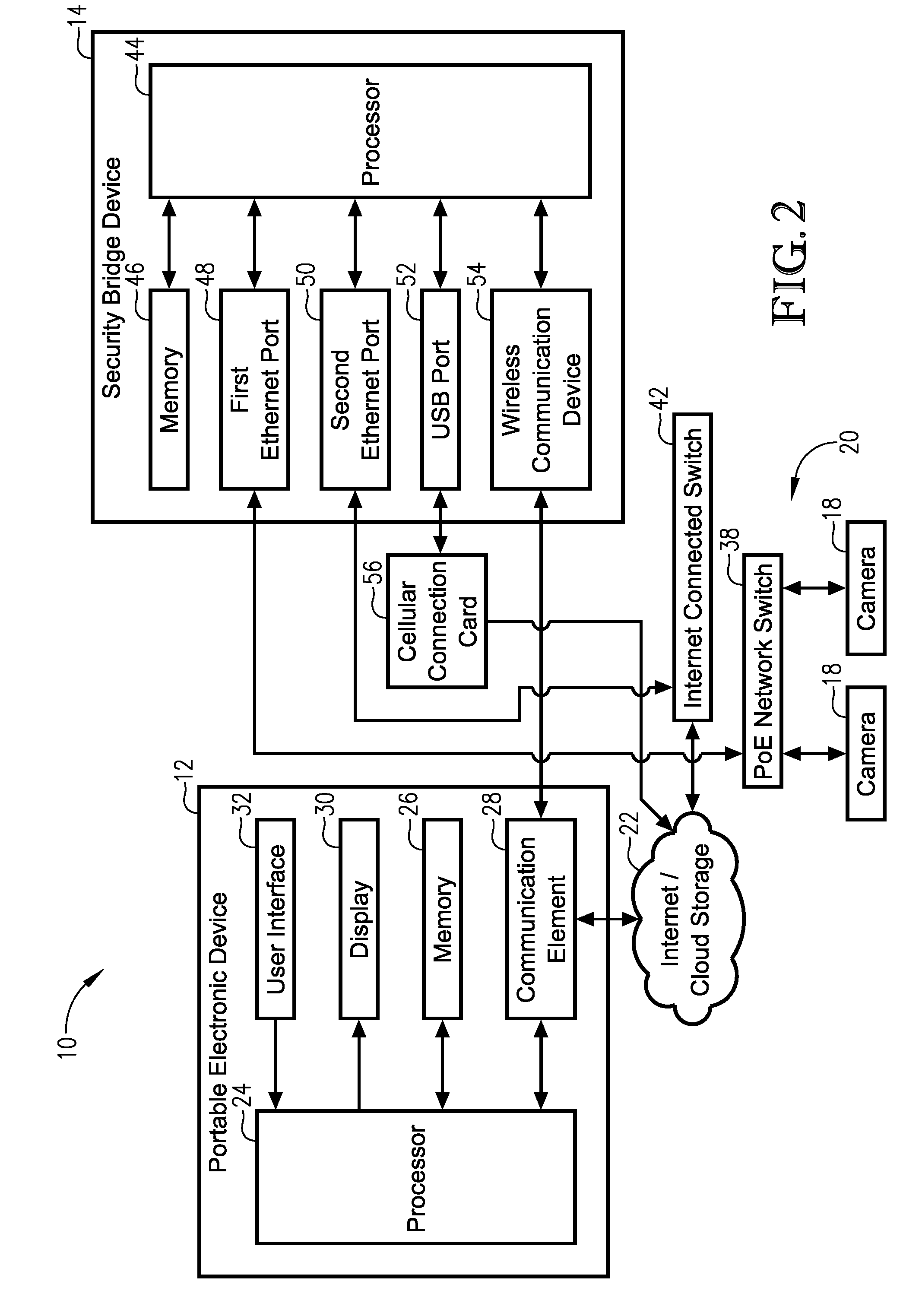
The invention provides a way to remotely view and adjust camera settings at the same time. This is done by connecting a security bridge device to a customer network and using a portable electronic device to receive video or still images from the company's cameras. The portable device can then display the images while adjusting the focus in real-time, giving the operator instant feedback on how the adjustments are affecting the images.

Problems solved by technology

This can be a time-consuming and labor-intensive process.
Furthermore, latency in the network between the security camera and the operator at the client work station can add to the difficulties of focusing the security camera in this traditional manner.
However, this method is also time-consuming, as it requires unplugging and subsequently rebooting the security camera to focus it.
Rebooting of the security camera can take a considerable amount of time.
This method also requires that the operator carry a laptop computer, which can be cumbersome, especially if the operator must climb a ladder to reach the security camera.
Many security cameras also have an inconvenient twisted pair cable connection location, complicating connection of the PoE break-out device and potentially causing undesired movement of the security camera when disconnecting the PoE break-out device.
In a dome camera, removal and subsequent replacement of the dome is not only time consuming, but may also knock the security camera out of focus when placed back onto the security camera.

Method used


Image

  • Method, computer program, and system for adjusting cameras
  • Method, computer program, and system for adjusting cameras
  • Method, computer program, and system for adjusting cameras

Examples


Embodiment Construction

[0019]The following detailed description of the invention references the accompanying drawings that illustrate specific embodiments in which the invention can be practiced. The embodiments are intended to describe aspects of the invention in sufficient detail to enable those skilled in the art to practice the invention. Other embodiments can be utilized and changes can be made without departing from the scope of the current invention. The following detailed description is, therefore, not to be taken in a limiting sense. The scope of the current invention is defined only by the appended claims, along with the full scope of equivalents to which such claims are entitled.

[0020]In this description, references to “one embodiment”, “an embodiment”, or “embodiments” mean that the feature or features being referred to are included in at least one embodiment of the technology. Separate references to “one embodiment”, “an embodiment”, or “embodiments” in this description do not necessarily ref...


PUM


Abstract

A system, method, and computer program for remotely viewing video or still images from one or more cameras on a customer network, providing real-time feedback on focus adjustments made by an operator. The system may include a security bridge device plugged into the customer network and a portable electronic device remotely located from the security bridge device. The security bridge device may auto-negotiate network settings with the customer network, automatically discover the cameras on the customer network, automatically / manually address and configure the cameras, and / or automatically / manually determine a best path for transmitting the video or still images. The portable electronic device may receive and display the video or still images from the cameras transmitted by the security bridge device via the determined best path. This allows the operator to focus one of the cameras while viewing the real-time video or still images therefrom.

Description

RELATED APPLICATIONS[0001]This application claims priority benefit of a provisional application entitled, “Method, Computer Program, and System for Adjusting Cameras,” Ser. No. 62 / 075,119, filed Nov. 4, 2014 and incorporated by reference herein in its entirety.BACKGROUND[0002]Security cameras are frequently used for remote monitoring of people, places, or things. Video and / or photos obtained by the security cameras may be stored and accessed locally on the security camera and / or may be controlled and accessed remotely by an operator with monitoring responsibilities. To focus or otherwise adjust the security cameras, two operators are traditionally required—one at a client work station viewing the transmitted video or photo feed, and one physically located at the security camera to manually focus the security camera. This can be a time-consuming and labor-intensive process. The operators typically communicate by phone, with the operator at the client work station describing adjustmen...

Claims


Application Information

Patent Timeline
Patent Type & Authority Applications(United States)
IPC IPC(8): H04N7/18H04N5/232G08B13/196
CPCH04N7/181H04N5/23212G08B13/19656G08B13/19682G08B13/19684
Inventor BOKOWSKI, CHADHOVANEC, MATTHEWBUMGARDNER, JAMIEKANNE, STEVEN
Owner WOW INSITES
Learn More