
Aircraft Electrical System Evaluation

Active Publication Date: 2008-02-14
ASTRONICS ADVANCED ELECTRONICS SYST
View PDF34 Cites 4 Cited by
  • Summary
  • Abstract
  • Description
  • Claims
  • Application Information

AI Technical Summary

Benefits of technology

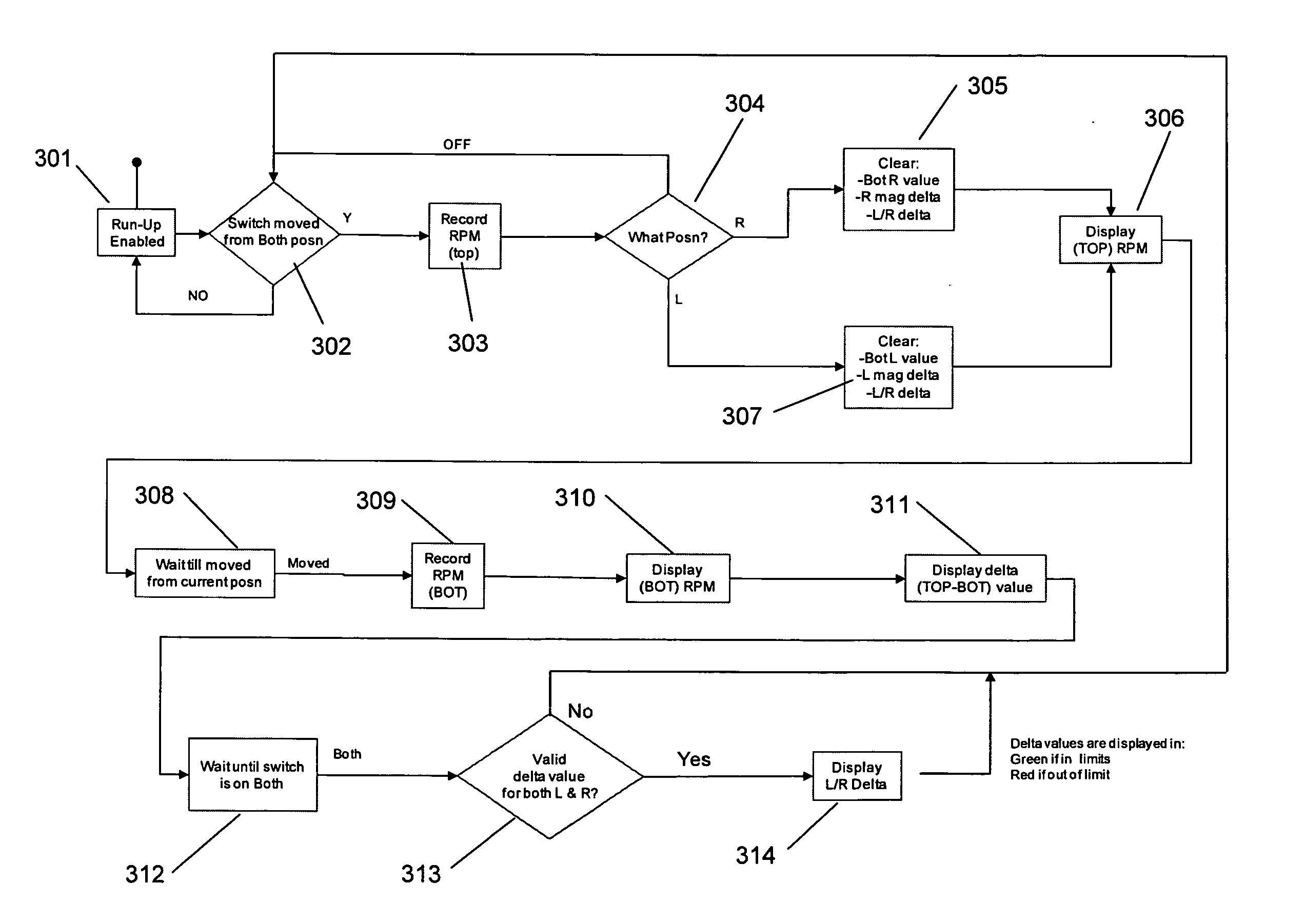
[0010] The present invention can provide a computer implemented function that monitors the position of a magneto switch in an aircraft to provide real-time feedback of engine RPM drop during a magneto check and communicates whether parameters are within limits. The function can also monitor engine and groundspeed / airspeed data in an aircraft to verify the magneto switch is in the correct position during engine start, takeoff and flight and can provide an alert to the pilot if the switch is not in the correct position. The automated magneto check function provides an easy way to test the operation of the aircraft's engine-driven magnetos and provides additional safety by alerting the pilot to unsafe positioning of the switch.

Problems solved by technology

This is unsafe because if the operating magneto fails, the other magneto is not operating because it is shorted.
Such a situation causes a complete engine failure.

Method used


Image

  • Aircraft Electrical System Evaluation
  • Aircraft Electrical System Evaluation
  • Aircraft Electrical System Evaluation

Examples


Embodiment Construction

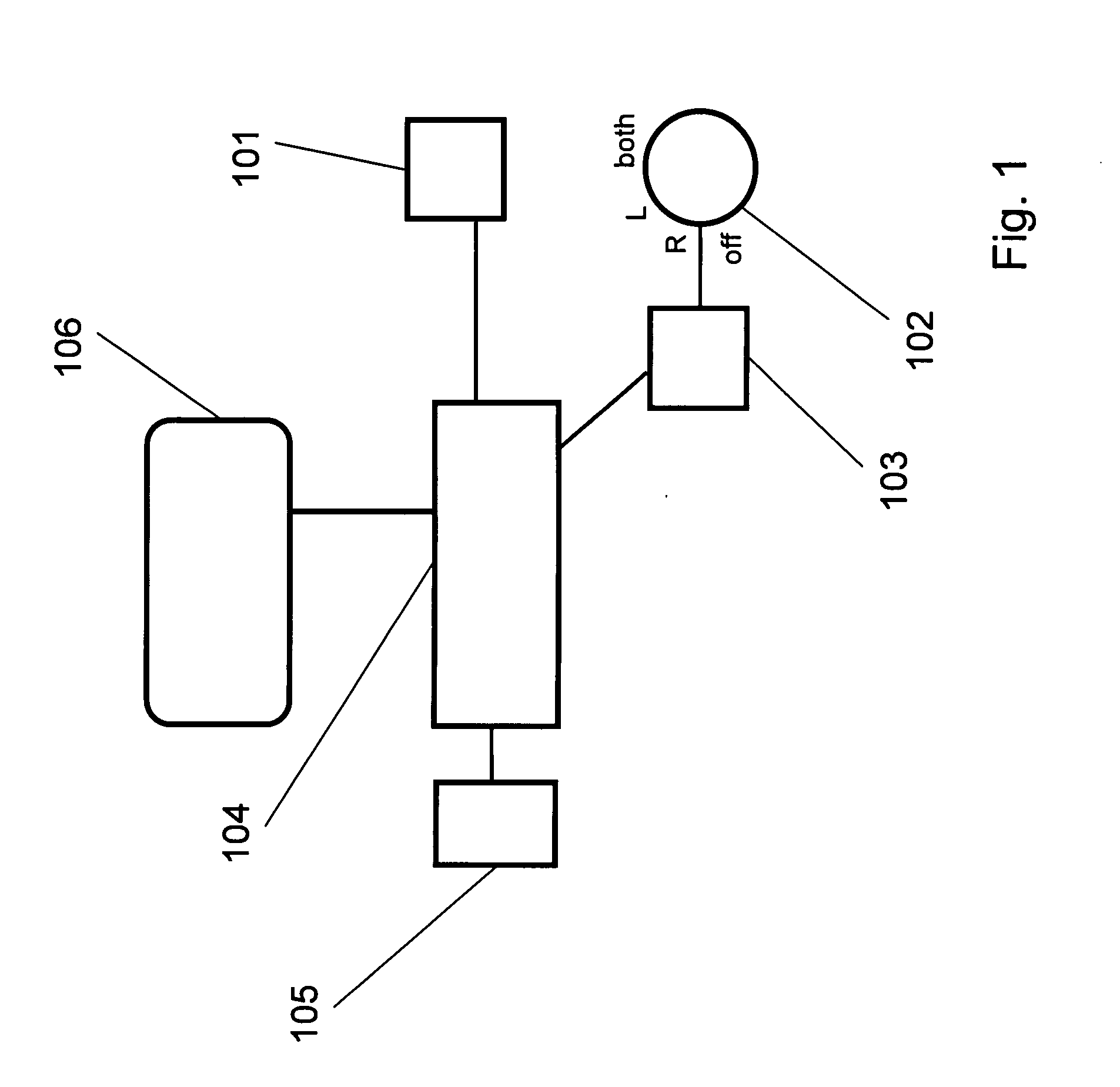
[0014]FIG. 1 is a schematic illustration of an example embodiment of the present invention. A sensor 101 is adapted to sense the operation rate of the engine, for example by sensing revolutions per minute or power output of the engine. A switch 102 is adapted to control the operation of two (or more) magnetos, for example by selectively shorting each magneto, or otherwise individually enabling each magneto to affect the operation of the engine. A sensor 103 senses the position of the switch 102 and communicates a signal representative of the position to a controller 104. Note that the sensor 103 can sense the switch 102 position directly, or indirectly, as an example by sensing the output of each magneto to discern whether the magneto is contributing to the operation of the engine. The controller 104 can control a memory device 105 and store in the memory device 104 information relating to the engine operation corresponding to operation with an individual magneto. The controller 104...


PUM


Abstract

A computer implemented function monitors the position of the magneto switch in an aircraft to provide real-time feedback of engine RPM drop during a magneto (mag) check and communicates whether parameters are within limits. The function can also monitor engine and groundspeed / airspeed data in an aircraft to verify the magneto switch is in the correct position during engine start, takeoff and flight and can provide an alert to the pilot if the switch is not in the correct position. The automated magneto check function provides an easy way to test the operation of the aircraft's engine-driven magnetos and provides additional safety by alerting the pilot to unsafe positioning of the switch.

Description

CROSS-REFERENCE TO RELATED APPLICATIONS [0001] This application claims the benefit of U.S. provisional application No. 60 / 853,712, filed Oct. 23, 2006, which is incorporated herein by reference. This application claims the benefit as a continuation-in-part of U.S. patent application Ser. No. 11 / 311,060, filed Dec. 19, 2005, which is incorporated herein by reference. This application is related to the following applications, each of which is incorporated herein by reference: Aircraft Emergency Handling, U.S. patent application Ser. No. ______, filed on the same date hereof; Backup Electrical Power System for Solid-State Aircraft Power Distribution Systems, U.S. patent application Ser. No. ______, filed on the same date hereof; Aircraft Exhaust Gas Temperature Monitor, U.S. patent application Ser. No. ______, filed on the same date hereof; Variable Speed Flap Retraction and Notification, U.S. patent application Ser. No. ______, filed on the same date hereof.FIELD OF THE INVENTION...

Claims


Application Information

Patent Timeline
IPC IPC(8): G08B21/00
CPCG01D7/00H02J2009/068H02J9/061G08B21/182G08B21/185G01D2207/10H02J9/068
Inventor AUSMAN, MARCDEVRIES, KEVIN
Owner ASTRONICS ADVANCED ELECTRONICS SYST
Learn More