
Rathchet Wrench with Dustproof Structure

Active Publication Date: 2016-05-12
HU BOBBY
View PDF2 Cites 6 Cited by
  • Summary
  • Abstract
  • Description
  • Claims
  • Application Information

AI Technical Summary

Benefits of technology

The patent describes a device called a dustproof ring that is used in a drilling machine. The dustproof ring is designed to prevent dust and debris from getting into the machine's gears and causing damage. The outer side of the ring is pressed against the abutment portion of the machine, while the inner side is spaced from it. The inner side has a lip that presses against a rod, and there is also a flange that prevents the ring from disengaging from the machine. This design helps to keep the machine clean and free of debris, which can cause damage to the machine.

Problems solved by technology

However, dirt can enter a gap between the pressing rod and the ratchet gear, impeding movement of the pressing rod relative to the ratchet gear.
Thus, the pressing rod cannot be operated to control engagement / disengagement of the socket after an amount of dirt is accumulated in the gap between the pressing rod and the ratchet gear, damaging the ratchet wrench.

Method used


Image

  • Rathchet Wrench with Dustproof Structure
  • Rathchet Wrench with Dustproof Structure
  • Rathchet Wrench with Dustproof Structure

Examples


Embodiment Construction

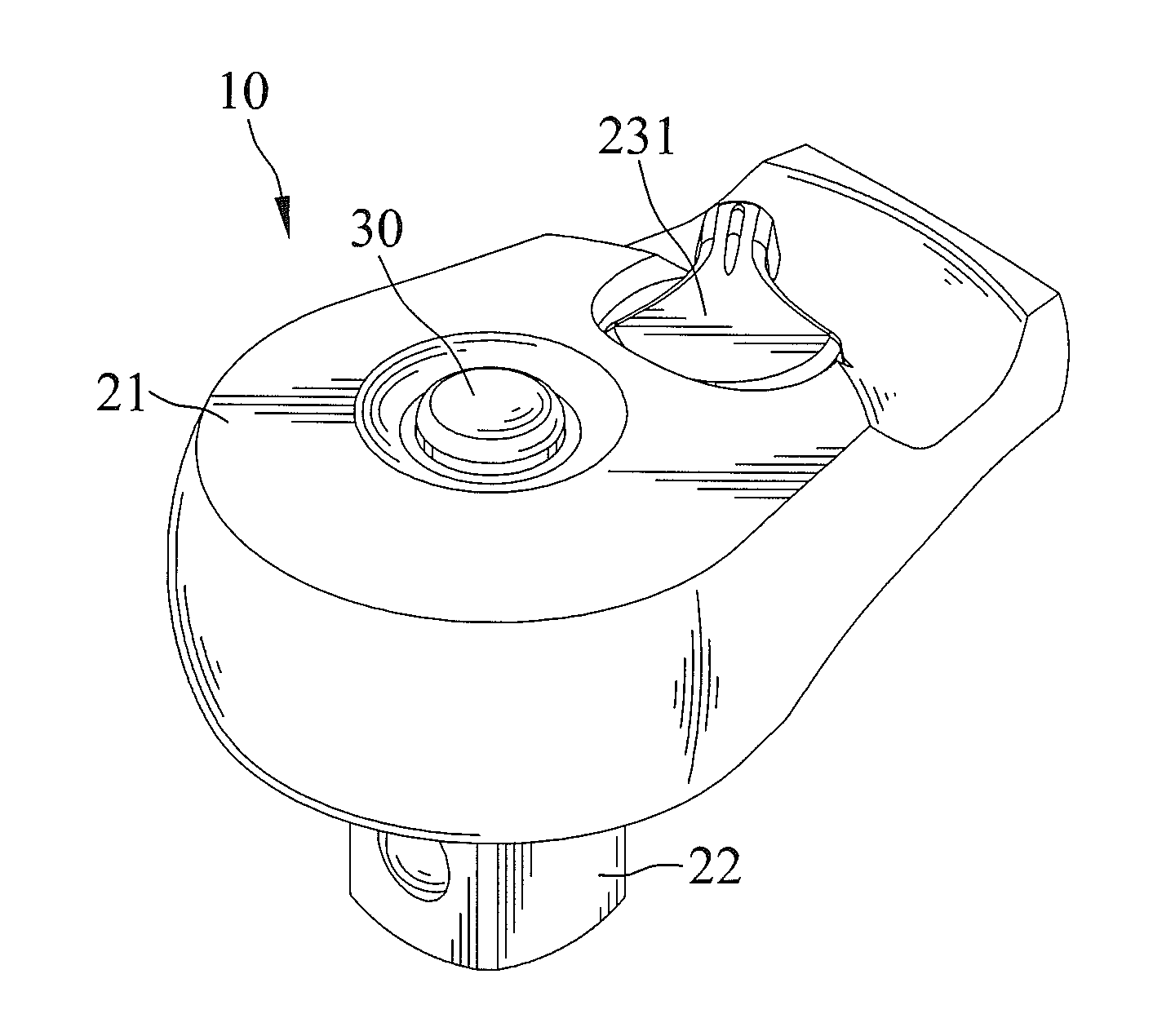
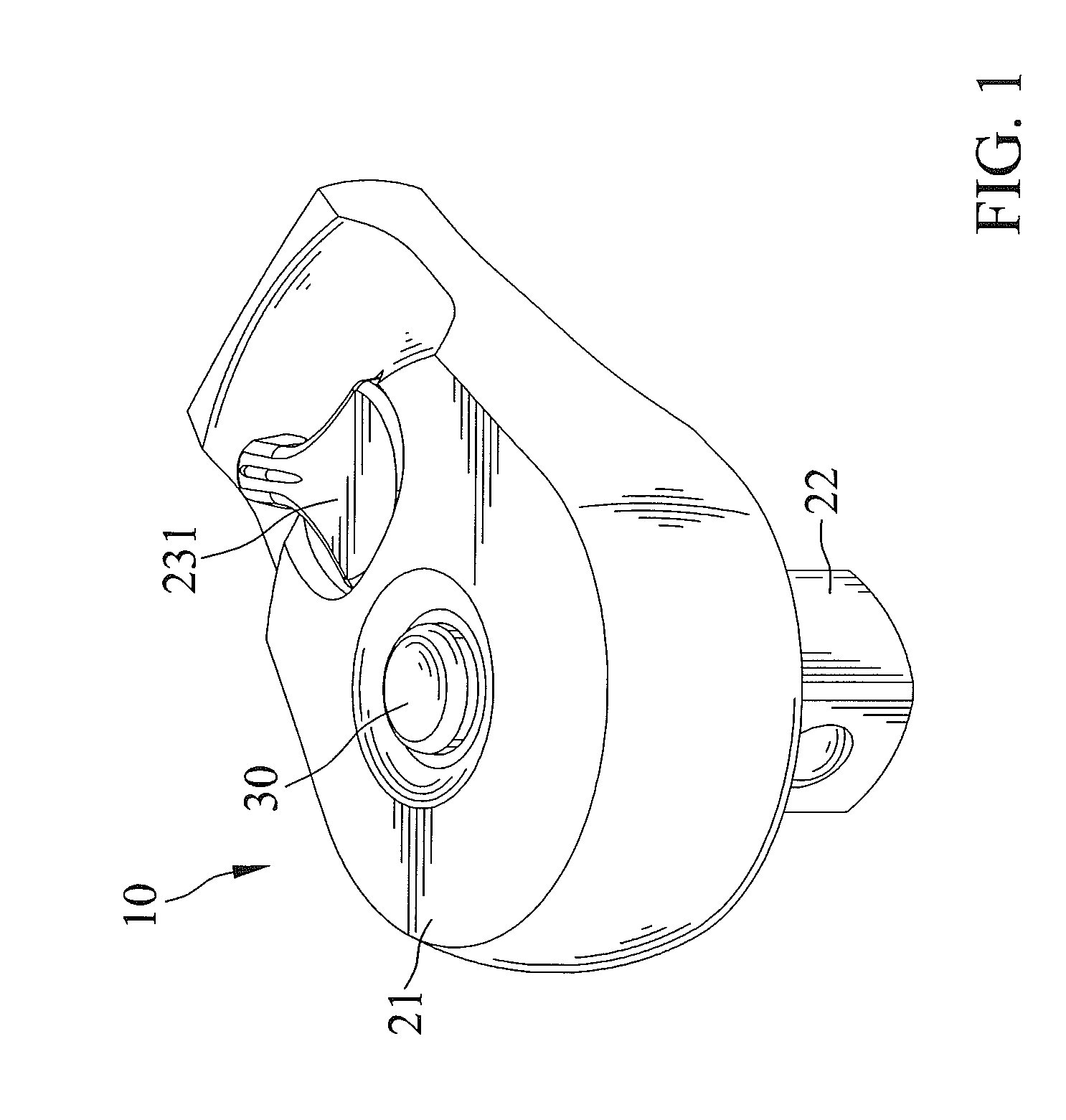
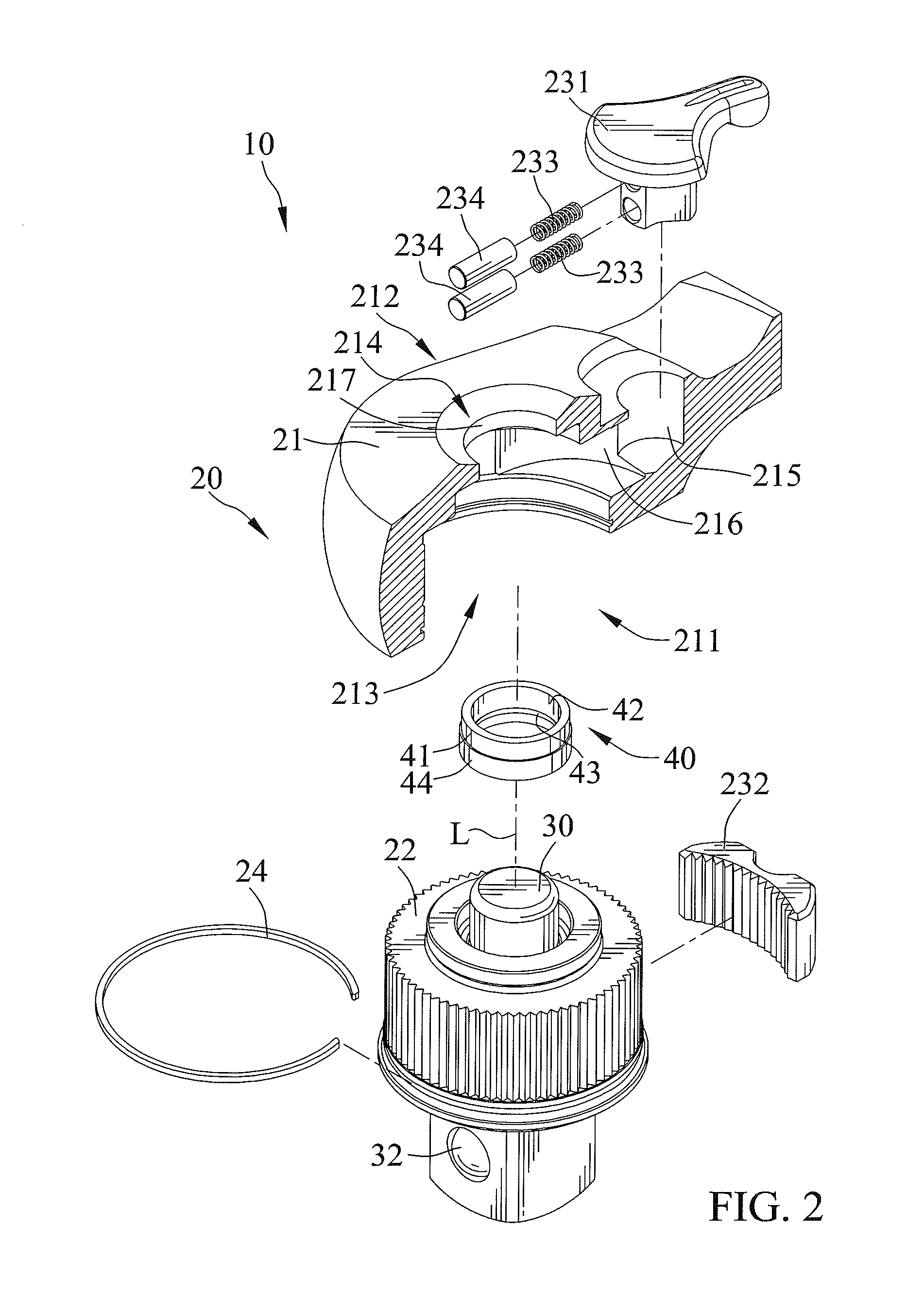
[0020]FIGS. 1-3 are a perspective view, an exploded view, and a cross sectional view of a ratchet wrench with a dustproof structure according to the present invention, respectively. Ratchet wrench 10 includes a driving device 20, a pressing rod 30, and a dustproof ring 40.

[0021]Driving device 20 includes a head 21 including first and second sides 211 and 212 spaced along a rotating axis L. Head 21 further includes a compartment 213 extending from first side 211 through second side 212. Compartment 213 is circular in cross section. A drive member 22 is received in compartment 213 and rotatable about rotating axis L. An end of drive member 22 is adapted to drive a tool, such as a socket. Compartment 213 includes a first face abutting with a second face of drive member 22 opposite to the end of the drive member 22. Second side 212 is axially spaced from first face of compartment 213 opposite to the end of drive member 22. Drive member 22 includes an annular protrusion extends axially f...


PUM


Abstract

A ratchet wrench includes a driving device having first and second sides spaced along a rotating axis. A compartment extends from the first side through the second side. A drive member is received in the compartment and includes an end for driving a tool. A ledge is formed on an inner periphery of an end of the compartment at the second side. A pressing rod extends into the drive member via the end of the compartment at the second side. The pressing rod is movable relative to the drive member along the rotating axis between a first position and a second position to control engagement with or detachment from the tool. A dustproof ring is mounted between the ledge and the pressing rod. The dustproof ring includes an outer side and an inner side. The outer side presses against an abutment portion of the ledge. The inner side presses against the pressing rod wherever the pressing rod is in the first position and the second position.

Description

[0001]The present application is a continuation-in-part application of U.S. patent application Ser. No. 13 / 712,102, filed on Dec. 12, 2012, of which the entire disclosure is incorporated herein.BACKGROUND OF THE INVENTION[0002]The present invention relates to a ratchet wrench with a dustproof structure and, more particularly, to a ratchet wrench including a dustproof ring mounted between a head and a pressing rod for providing a dustproof effect.[0003]U.S. Pat. No. 7,311,019 discloses a ratchet wrench including a head and a handle connected to the head. The head includes top and bottom ends, with a through cavity formed in the head from the top end to the bottom end. A ratchet gear is disposed in the through cavity. A cover plate is mounted to the bottom end of the head, and a ledge is formed on the top end of the head, preventing the ratchet gear from disengaging from the head. The ratchet gear includes a hole receiving a pressing rod operable to control engagement with or disengag...

Claims


Application Information

Patent Timeline
IPC IPC(8): B25B13/46
CPCB25B13/463
Inventor HU, BOBBY
Owner HU BOBBY
Learn More