Supercharge Your Innovation With Domain-Expert AI Agents!

Display control apparatus and computer-readable recording medium

a control apparatus and recording medium technology, applied in the field of display control apparatus and computer-readable recording medium, can solve problems such as the difficulty of user grasping the relationship between the display and the display

Inactive Publication Date: 2016-05-12
RICOH KK
View PDF37 Cites 52 Cited by
  • Summary
  • Abstract
  • Description
  • Claims
  • Application Information

AI Technical Summary

Benefits of technology

The present invention makes it easy to see the relation between the display range of an image on a screen and the information that indicates a list of viewpoints on the image.

Problems solved by technology

However, with the conventional techniques, it has been difficult for a user to grasp relation between a display range of an image that is currently displayed on a screen and information indicating a list of viewpoints on the image.

Method used


Image

  • Display control apparatus and computer-readable recording medium
  • Display control apparatus and computer-readable recording medium
  • Display control apparatus and computer-readable recording medium

Examples


first embodiment

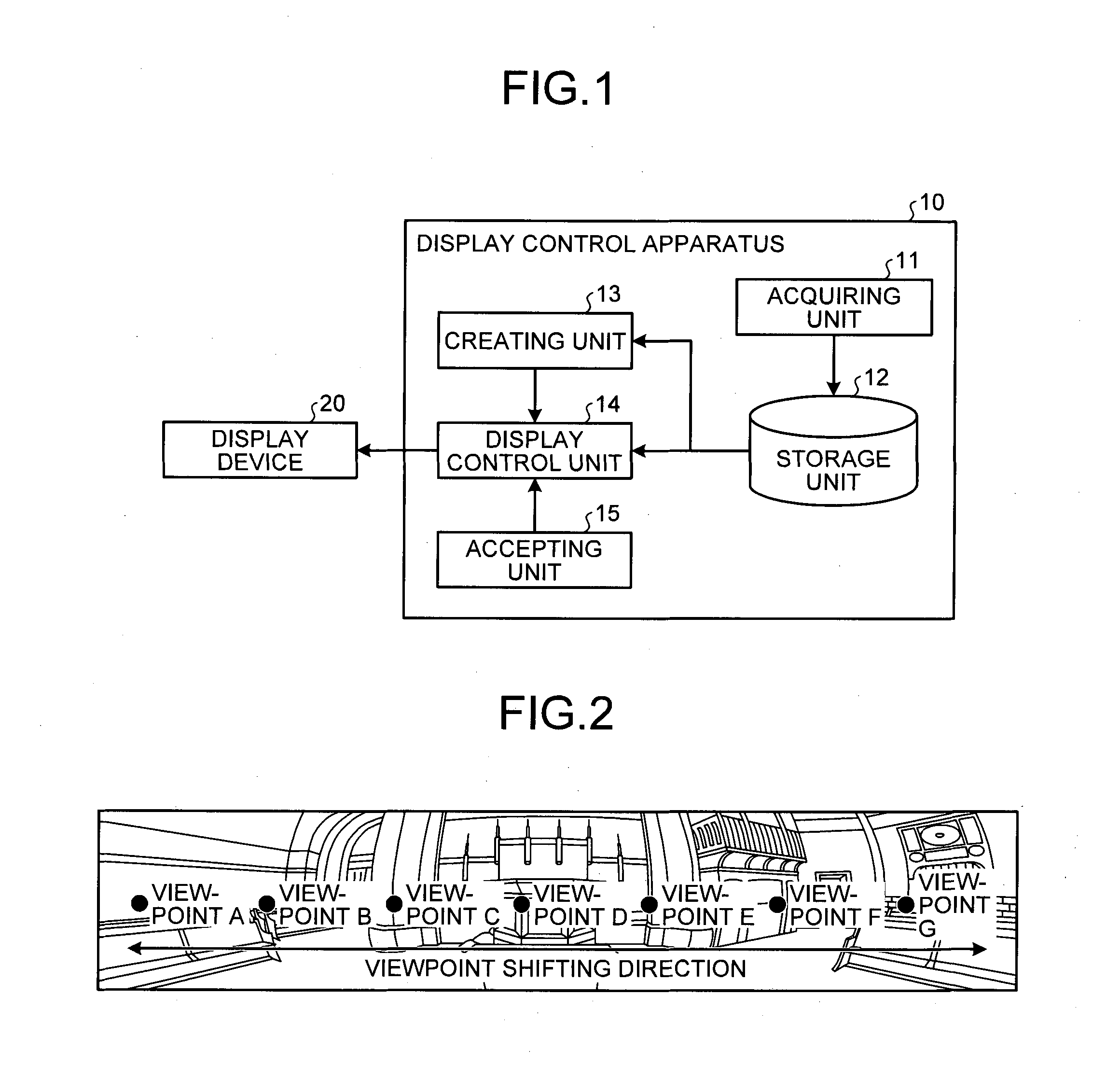
[0026]FIG. 1 is a block diagram illustrating an example of a configuration of a display control apparatus 10 of a first embodiment of the present invention. The display control apparatus 10 of the present embodiment includes an acquiring unit 11, a storage unit 12, a creating unit 13, a display control unit 14, and the accepting unit 15. The display control apparatus 10 is connected to a display device 20. The display control apparatus 10 controls images (hereinafter, “display image”) displayed on the display device 20.

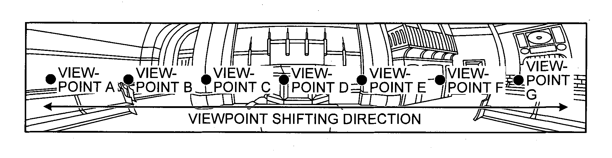
[0027]The acquiring unit 11 acquires an omnidirectional image that is an image of all directions at an imaging spot from an external device such as an imaging device that can create the omnidirectional image. Equipment of, for example, an imaging unit that images all directions at an imaging spot using two pieces of fish-eye lenses facing opposite directions from each other and a creating unit that combines two pieces of images that are imaged by the two pieces of fis...

second embodiment

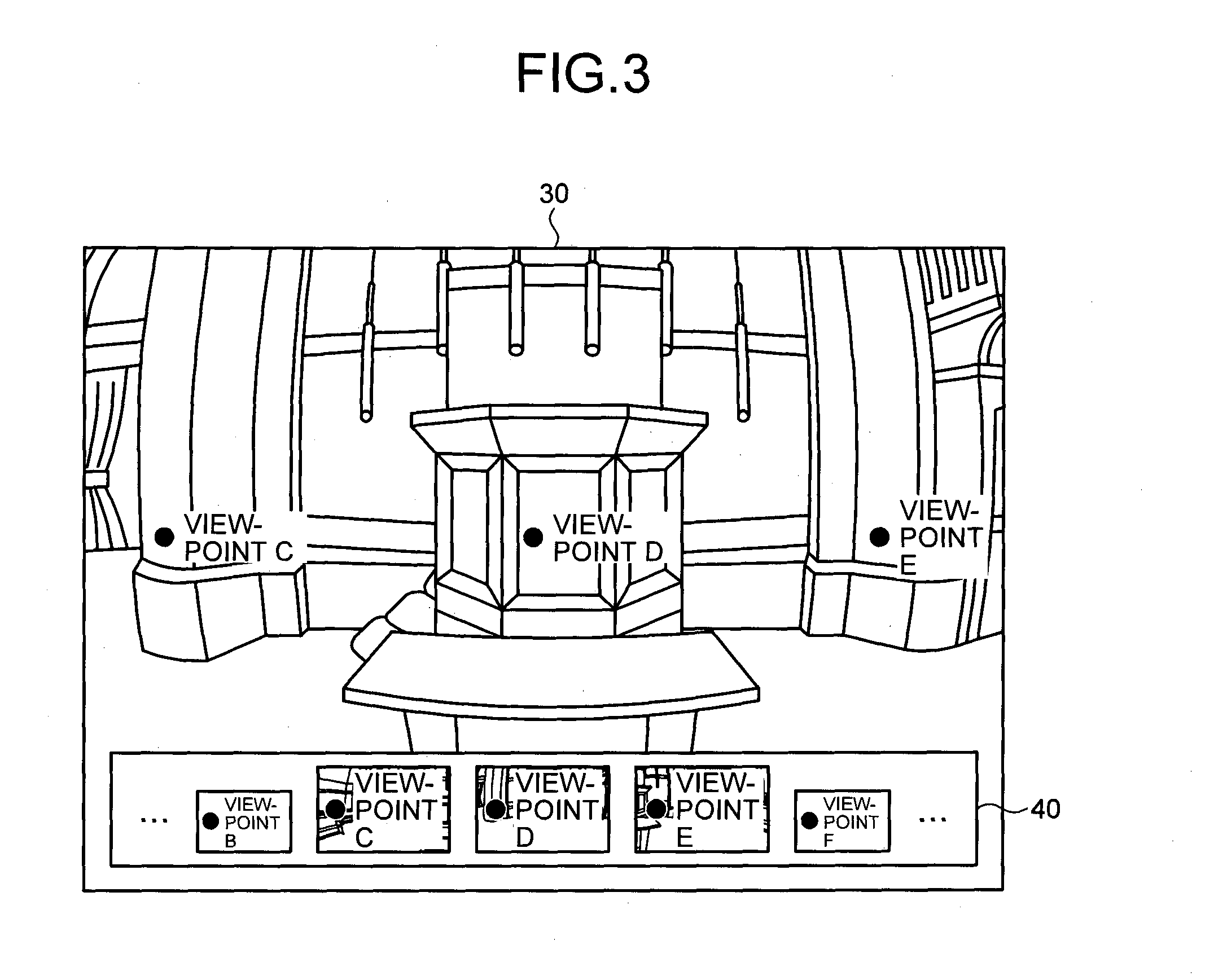
[0068]Next, the display control apparatus 10 of a second embodiment is explained. The display control unit 14 in the display control apparatus 10 of the present embodiment makes the size of thumbnails of partial omnidirectional images including, in the center, viewpoints that are included in an omnidirectional image of the display image smaller than thumbnails of partial omnidirectional images including viewpoints that are not include in the omnidirectional image of the display image in the center. That is, while the display control apparatus 10 of the first embodiment emphasizes, in the viewpoint listing image, thumbnails of viewpoints that are displayed on the display device 20, the display control apparatus 10 of the second embodiment emphasizes, in the viewpoint listing image, thumbnails of viewpoints that are not displayed on the display device 20.

[0069]Because the configuration of the display control apparatus 10 of the present embodiment is the same as that of the display con...

third embodiment

[0074]Next, the display control apparatus 10 of a third embodiment is explained. The display control unit 14 in the display control apparatus 10 of the present embodiment differs from the display control apparatus 10 of the first embodiment in that the display control unit 14 controls display when multiple viewpoints not only the azimuth of which but also the angle of elevation of which vary are present. Because the configuration of the display control apparatus 10 of the present embodiment is the same as that of the display control apparatus 10 of the first embodiment, explanation thereof is omitted. Moreover, because explanation of the present embodiment is similar to the explanation of the first embodiment, differences from the first embodiment are specifically explained based on a specific example.

[0075]FIG. 13 is a table indicating an example of viewpoint listing information of the display control apparatus 10 of the third embodiment. The viewpoint listing information includes,...


PUM


Abstract

A display control apparatus including: a creating unit that creates, from an image, a partial image of the image, and including in a center thereof an arbitrary viewpoint on the image; a display controller that displays, on a display, a display image including the image and a viewpoint listing image of a list of thumbnails of plural of the partial images; and an accepting unit that accepts input indicating a change of the image in the display image, according to operation on the image or the viewpoint listing image. The display controller changes the image in the display image according to the input, and changes a sequential order of the thumbnails in the viewpoint listing image such that a thumbnail of the partial image corresponding to a region of the image to be newly displayed according to the input is displayed at a predetermined position in the viewpoint listing image.

Description

TECHNICAL FIELD[0001]The present invention relates to a display control apparatus and a computer-readable recording medium.BACKGROUND ART[0002]A technique in which images of all directions at an imaging spot are imaged to make an omnidirectional view at the imaging spot into one piece of image has been known. For example, in Patent Literature 1, the invention of an observation device that converts images of all directions at an imaging spot into an image for display, and displays the image for display on a display unit of a cylindrical casing is disclosed. Moreover, a technique in which a part of an image in which all directions at an imaging spot are put into one piece of image is displayed on a display of a personal computer in such a form that a predetermined direction is actually viewed from an imaging spot has been known. Furthermore, a technique of changing a display range (direction) of an image arbitrarily according to the operation of a user has been known.[0003]However, wi...

Claims


Application Information

Patent Timeline
Patent Type & Authority Applications(United States)
IPC IPC(8): G06T3/40G06F3/0485H04N5/262G06F3/048G06F3/0481G06F3/0484
CPCG06T3/40G06F3/0485H04N5/2628H04N5/2621G06F3/04815A63F13/5255G06F3/048
Inventor FUKUSHI, SEIICHIRO
Owner RICOH KK
Features
  • R&D
  • Intellectual Property
  • Life Sciences
  • Materials
  • Tech Scout
  • Unparalleled Data Quality
  • Higher Quality Content
  • 60% Fewer Hallucinations
Learn More