
High stiffness and high access forming tool for incremental sheet forming

a technology of incremental sheet forming and forming tools, which is applied in the direction of manufacturing tools, drawing profiling tools, drawing mandrels, etc., can solve the problems of known systems being prone to breakage, forming tools not always reaching the desired level of dimensional accuracy, and casting a die is an expensive process, so as to avoid the interference of tool shank to workpi

Active Publication Date: 2016-05-19
FORD GLOBAL TECH LLC
View PDF15 Cites 8 Cited by
  • Summary
  • Abstract
  • Description
  • Claims
  • Application Information

AI Technical Summary

Benefits of technology

The patent text describes a forming tool for sheet metal that uses multiple spheres of different diameters. This allows for a smaller sphere to be used for the initial pass of the sheet metal, followed by a larger sphere for more accurate shaping. This tool avoids the need for multiple tools between passes and also avoids breakage during the forming process. Overall, this tool provides an efficient and practical method of incremental sheet forming that improves the quality of the finished product.

Problems solved by technology

However, casting a die is an expensive process.
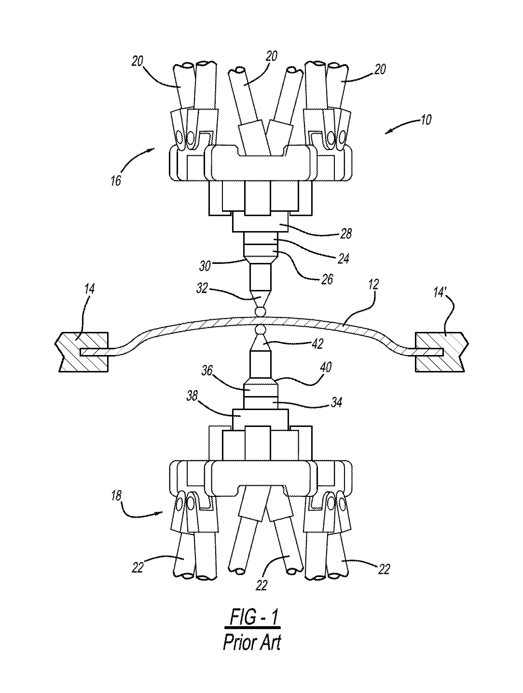
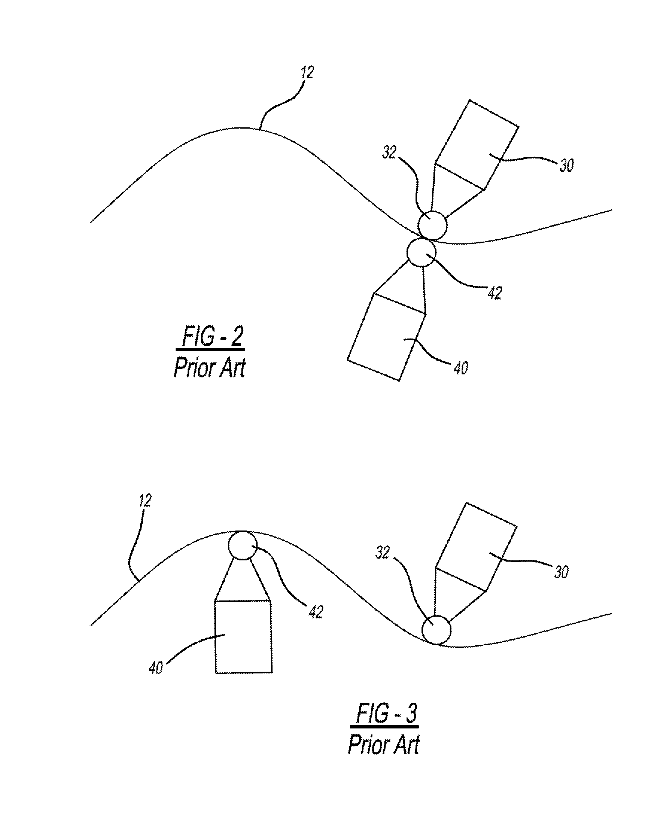
However, known forming tools do not always achieve the desired level of dimensional accuracy because such tools have large shanks that may interfere with formation of the metal workpiece through unintended contact with the vertical walls of the workpiece during the forming process.
Another hindrance to achieving the desired level of dimensional accuracy is that that that known tools have shanks that are tapered to meet the round tip and, as a consequence, the tip-to-shank interface is the weakest point on the load path of the entire forming machine.
Known systems are thus prone to breakage at this point caused by stiffness of the forming tool and the inherent weakness of the tip-to-shank interface, a weakness that becomes particularly pronounced when deflection is experienced during the forming process.

Method used


Image

  • High stiffness and high access forming tool for incremental sheet forming
  • High stiffness and high access forming tool for incremental sheet forming
  • High stiffness and high access forming tool for incremental sheet forming

Examples


first embodiment

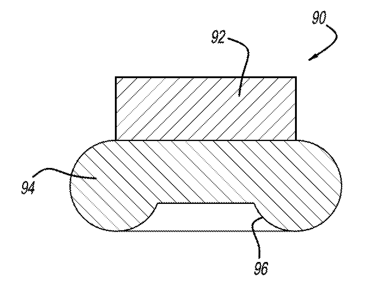
[0052]Referring to FIGS. 6 through 8D, variations of the disclosed inventive concept are illustrated. The common features of the illustrated variations of the incremental forming tool include a shank for attachment to a unit such as a CNC machine or a robotic arm, donut-shaped forming tool, and an adaptor that functions as the interface between the shank and the donut-shaped forming tool. While three individual components are illustrated, it is to be understood that the incremental forming tool of FIGS. 6 through 8D may be formed from a solid piece. The forming tool of the disclosed inventive concept may be used for forming any suitable material or materials that have desirable forming characteristics, such as a metal, metal alloy, polymeric material, or combinations thereof.

[0053]The most important feature of the incremental forming tool of FIGS. 6 through 8D is the use of the donut-shaped component as the forming element instead of the ball-end tip of the prior art. This design pr...

second embodiment

[0061]FIGS. 9A and 9B illustrate the disclosed inventive concept. As illustrated in these figures, a multi-tip forming tool, generally illustrated as 120, is shown. The multi-tip forming tool 120 includes an adapter 122 to which a plurality of donut-shaped metal forming tips, including donut-shaped tip 124, donut-shaped tip 126, and donut-shaped tip 128 are attached. The donut-shaped tip 124 is attached to the adapter 122 by an arm 130. The donut-shaped tip 126 is attached to the adapter 122 by an arm 132. The donut-shaped tip 128 is attached to the adapter 122 by an arm 134. The adapter 122 is attached to a shank 136. The arms 130, 132 and 134 function as positioning axes.

[0062]The donut-shaped tips 124, 126 and 128 according to this embodiment are of different diameters. For example, the donut-shaped tips 124, 126 and 128 can range from 6 mm to 25 mm in diameter. By providing a single forming tool 120 having tips of different sizes, the need for changing forming tools during the f...

third embodiment

[0063]FIGS. 10A and 10B illustrate the disclosed inventive concept. As illustrated in these figures, a multi-ball tip forming tool, generally illustrated as 140, is shown. The multi-ball tip forming tool 140 includes a shank 142 to which is attached a donut-shaped body 144. Extending outwardly from the donut-shaped body 144 is a plurality of metal forming ball-end tips, including ball-end tip 146, ball-end tip 148, and ball-end tip 150. The ball-end tips 146, 148, and 150 are of different diameters. For example, the ball-end tips 146, 148 and 150 can range from 6 mm to 25 mm in diameter. By providing a single forming tool 140 having tips of different sizes, the need for changing forming tools during the forming operation is avoided as the smaller ball-end tip 146 may be used for the first contouring pass on the workpiece, the intermediate-sized ball-end tip 150 may be selected for the second pass, and the largest ball-end tip 148 may be selected for the final pass.

[0064]The forming ...


PUM

PropertyMeasurementUnit
diameteraaaaaaaaaa
diameteraaaaaaaaaa
diameteraaaaaaaaaa

Abstract

An tool for the incremental forming of material sheeting is disclosed. The tool comprises a forming tip, a shank, and an interface adapter positioned between the forming tip and the shank. The forming tip has a diameter and the shank has a diameter. The diameter of the forming tip is greater than the diameter of the shank. The forming tip may be of a variety of configurations. The forming tip may be donut-shaped. The donut-shaped tip may have a recessed area formed therein. The recessed area may be frustoconically shaped. As an alternative to the forming tip being donut-shaped, the forming tip may be made up of at least two forming spheres. An adapter is provided to which the spheres may be attached either directly or by arms. The diameters of the spheres may be the same or may be different diameters.

Description

TECHNICAL FIELD[0001]The disclosed inventive concept relates generally to tools for the incremental forming of sheets of material. More particularly, the disclosed inventive concept relates to tools used to assure dimensional accuracy and accessiblity in incrementally formed workpieces.BACKGROUND OF THE INVENTION[0002]Several methods of forming sheet metal are known. A common method of forming sheet metal is stamping through the use of a die. However, casting a die is an expensive process. While a popular method of metal forming, the use of a die has certain disadvantages.[0003]A variant of the use of a die in the formation of a metal workpiece is through a deep drawing process. In this process, a sheet metal blank is radially drawn into a forming die through the use of a punch.[0004]Another known method of forming a workpiece is by way of incremental sheet forming. This is a technique where a metal sheet is formed step-wise into a finished workpiece by way of a series of relatively...

Claims


Application Information

Patent Timeline
Patent Type & Authority Applications(United States)
IPC IPC(8): B21D31/00
CPCB21D31/005B21D22/02B21D37/00B21D37/16B21D22/14
Inventor KIRIDENA, VIJITHA SENAKAXIA, ZHIYONG CEDRICREN, FENG
Owner FORD GLOBAL TECH LLC
Learn More