Ball Joint Connection

Inactive Publication Date: 2016-05-19
HELLA KGAA HUECK & CO
View PDF6 Cites 6 Cited by
  • Summary
  • Abstract
  • Description
  • Claims
  • Application Information

AI Technical Summary

Benefits of technology

[0008]In one embodiment, two tabs are arranged opposite each other. By this means, the load applied by the tabs is symmetrical, so that the assembly of the ball head is facilitated.
[0009]In a further embodiment an angle α between a plane across the outer region of the opening and the tab is between 45° and 70°. Any try to pull the joint ball out of the ball socket reduces a bending moment acting upon the tab. Therefore, pulling out is only possible via destruction of the ball joint connection.
[0010]In a further embodiment, the ball socket has a recess in the region of the tab. By this means, the tab can yield into this recess, thus mi

Problems solved by technology

As the tab shows a predetermined stiffness—especially because of its dimensions in combination with the material properties relating to forces applied in parallel to its surface—it is impossible or very difficult for the tab to yield to the joint ball when an attempt is made to pull it out of the ball

Method used


Image

  • Ball Joint Connection
  • Ball Joint Connection
  • Ball Joint Connection

Examples


Example

DETAILED DESCRIPTION OF THE DRAWINGS

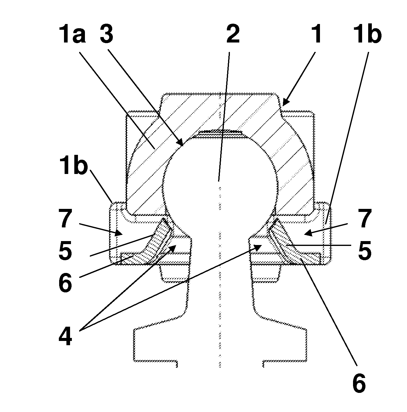
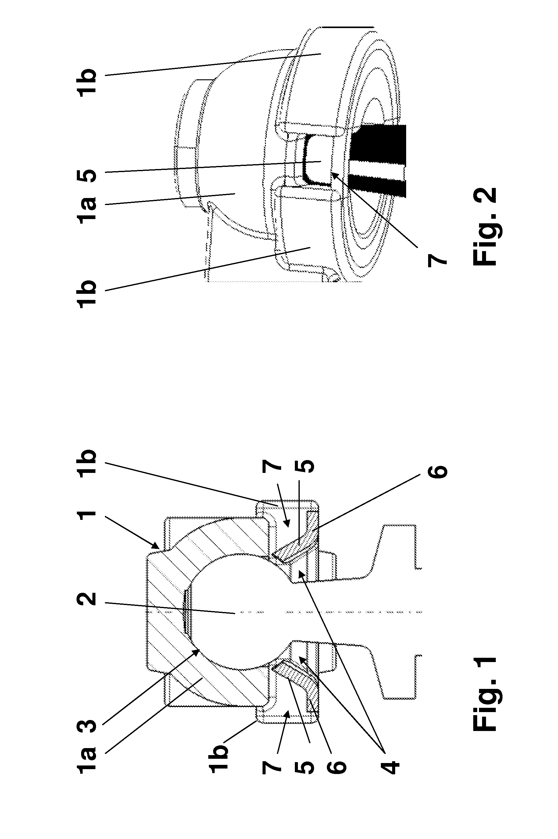
[0018]As can be seen in FIGS. 1 and 2, a ball joint connection comprises a ball socket 1 and a joint ball 2.

[0019]The ball socket 1 has a head piece 1a with a recessed ball segment-shaped opening 3. A plane cut surface of the ball segment forms an opening open toward the outside for the joint ball 2. In the region of the cut surface, a reinforcing ring 1b is molded onto the head piece 1a and encloses a frustrum-shaped open space 4, which abuts to the cut surface and widens toward the outside. Therefore, the opening 3 and the free space 4 form a unit.

[0020]A coupling rod, which is not represented, being fastened or linked to an assigned device on its end pointing away from the ball socket 1, is attached to the ball socket 1.

[0021]The entire ball socket 1 comprising the head piece 1a and the reinforcing ring 1b is integrally formed, e.g. made from injection-molded plastic material. Preferentially, the coupling rod with the ball socket 1 and the fast...


PUM


Abstract

A ball joint connection with a ball socket in which a ball segment-shaped opening is formed, and a joint ball is rotatably supported and snap-fitted in the ball socket. The joint ball shall be inserted in a ball socked with little effort, but can be removed only with a major effort or not at all in a nondestructive manner. To this end, below the opening, at least one rigid tab is fastened in the ball socket which, in a rest position, extends so far in the direction of the opening that it has a predetermined distance to the mounted joint ball. The tab is spring-elastically movable from the rest position during the assembly of the joint ball.

Description

CROSS REFERENCE[0001]This application claims priority to German Application No. 10 2014 116686.8, filed Nov. 14, 2014, the entirety of which is hereby incorporated by reference.FIELD OF TECHNOLOGY[0002]The invention relates to a ball joint connection with a ball socket in which a ball segment-shaped opening is formed, and a joint ball being rotatably supported and snap-fitted in the ball socket.BACKGROUND[0003]In principle, such ball joint connections are known and they are generally used e.g. for the mechanical transmission of forces in a connection between a rod and a moving part. In automotive engineering, ball joint connections are e.g. known in connection with a coupling rod being arranged for the connection between a car body and a sensor, e.g. to determine a level (deflection) and / or an inclination angle.[0004]From DE 295 06 202 U1, a ball joint connection is known, which is made from a ball socket and a joint ball. The ball socket is manufactured separately from a rod carry...

Claims


Application Information

Patent Timeline
IPC IPC(8): F16C11/06
CPCF16C11/06F16C11/0657F16C11/069F16C2240/30
Inventor ELPERMAN, THOMASZYWITZKI, JOHANNES
Owner HELLA KGAA HUECK & CO
Why Eureka
Try Eureka