Curved liquid crystal display panel and curved liquid crystal display apparatus

a liquid crystal display and liquid crystal display technology, applied in the field ofdisplays, can solve problems such as deteriorating the display quality of the lcd, and achieve the effects of preventing the color shifting phenomenon, deteriorating the display quality of the lcd, and different widths

Active Publication Date: 2016-05-19
SHENZHEN CHINA STAR OPTOELECTRONICS TECH CO LTD
View PDF1 Cites 9 Cited by
  • Summary
  • Abstract
  • Description
  • Claims
  • Application Information

AI Technical Summary

Benefits of technology

[0026]In the conventional curved LCD panel and apparatus, the color shifting phenomenon results from a shifted distance between the color filter substrate and the array substrate, thereby deteriorating a display quality of the LCD. In comparison to the prior art, the black matrix in the curved LCD panel and the curved LCD apparatus of the present invention can have different widths in the different regions to prevent the color shifting phenomenon.

Problems solved by technology

In the conventional curved LCD panel and apparatus, the color shifting phenomenon results from a shifted distance between the color filter substrate and the array substrate, thereby deteriorating a display quality of the LCD.

Method used


Image

  • Curved liquid crystal display panel and curved liquid crystal display apparatus
  • Curved liquid crystal display panel and curved liquid crystal display apparatus
  • Curved liquid crystal display panel and curved liquid crystal display apparatus

Examples


first embodiment

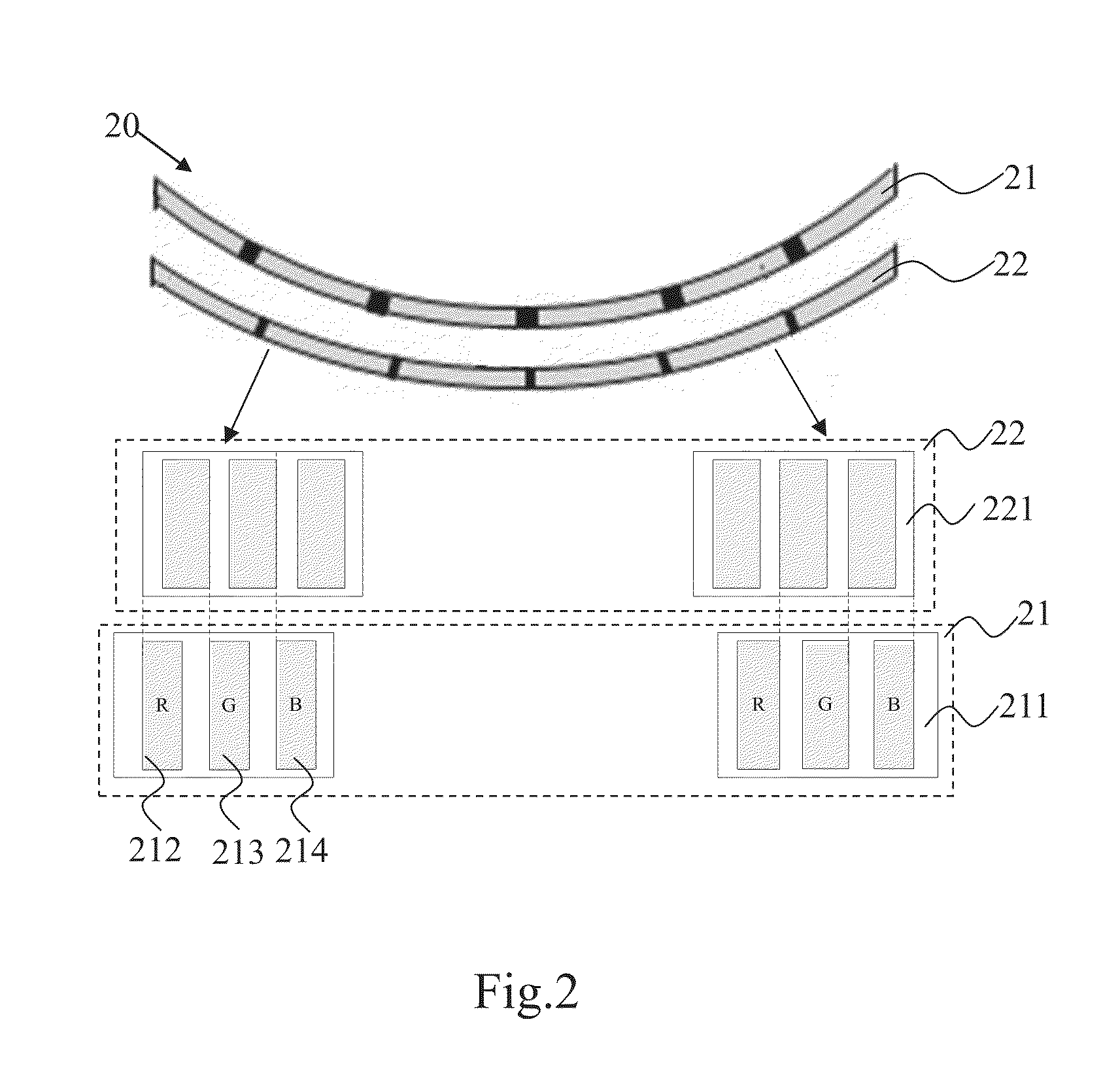
[0034]Referring to FIG. 2, a schematic diagram and a partially structural view showing a curved LCD according to the present invention are illustrated therein. The curved LCD panel 20 of the present embodiment comprises a cured color filter substrate 21 and a cured array substrate 22.

[0035]As shown in FIG. 2, the color filter substrate 21 comprises a black matrix 211 and color filters, and the color filters comprise red filters 212, green filters 213, and blue filters 214. The array substrate 22 is opposite the color filter substrate 21 and comprises pixel electrodes 221, data lines (not shown), and scan lines (not shown). The pixel electrodes 221 of the array substrate 22 correspond to the color filters of the color filter substrate 21, respectively. The light rays from the pixel electrodes and passing through the color filter substrate 21 can be red, green, or blue.

[0036]As shown in FIG. 2, the cured color filter substrate 21 is opposite the cured array substrate 22, and the color...

second embodiment

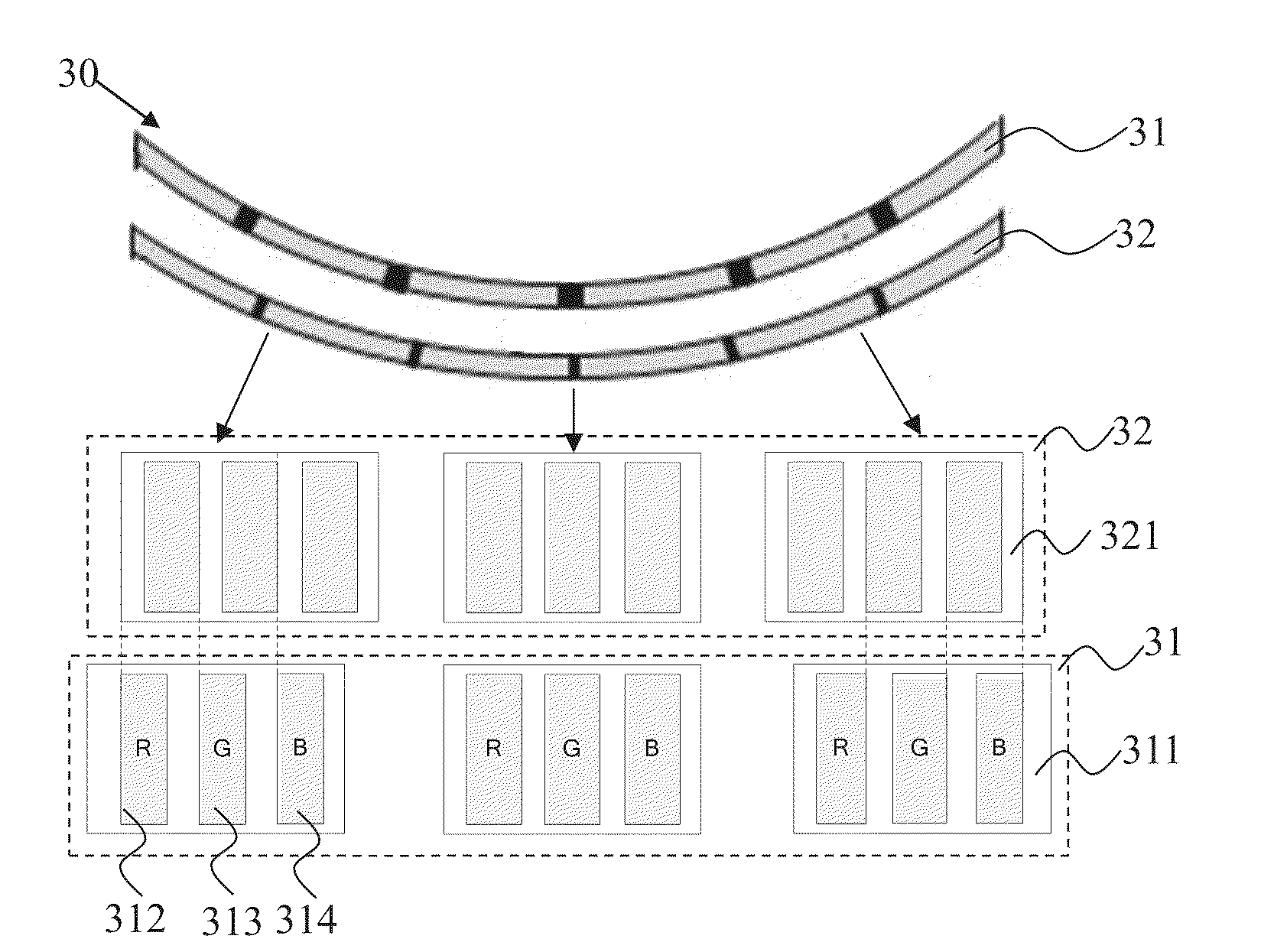
[0040]Referring to FIG. 3, a schematic diagram and a partially structural view showing a curved LCD according to the present invention are illustrated. The curved LCD panel 30 of the present embodiment comprises a cured color filter substrate 31 and a cured array substrate 32.

[0041]As shown in FIG. 3, the color filter substrate 31 comprises a black matrix 311 and color filters, and the color filters comprise red filters 312, green filters 313, and blue filters 314. The array substrate 32 is opposite the color filter substrate 31 and comprises pixel electrodes 321, data lines (not shown), and scan lines (not shown). The pixel electrodes 321 of the array substrate 32 correspond to the color filters of the color filter substrate 31, respectively. The light rays from the pixel electrodes and passing through the color filter substrate 31 can be red, green, or blue.

[0042]As shown in FIG. 3, the cured color filter substrate 31 is opposite the cured array substrate 32, and the color filters...


PUM

PropertyMeasurementUnit
widthaaaaaaaaaa
brightnessaaaaaaaaaa
distanceaaaaaaaaaa

Abstract

A curved LCD panel is provided. The curved LCD panel comprises a curved color filter substrate and a cured array substrate. A plurality of regions are formed along a longitudinal direction of the color filter substrate. In each of the regions of the color filter substrate, according to a greatest shifted distance between the color filter and the array substrate, a width of the black matrix within the region is predetermined. The black matrix can have different widths in the different regions to prevent the color shifting phenomenon.

Description

FIELD OF THE INVENTION[0001]The present invention relates to a technical field of displays, and more particularly to a curved liquid crystal display (LCD) panel and a curved LCD apparatus.BACKGROUND OF THE INVENTION[0002]A curved LCD is an LCD with a cured structure, comprising a cured color filter substrate 11 and a cured array substrate 12. The color filter substrate 11 can comprise a black matrix 111, red filters 112, green filters 113, and blue filters 114. Refer to FIG. 1, which is a schematic diagram and a partially structural view showing a conventional curved LCD are illustrated.[0003]The black matrix 111 on the color filter substrate 11 is configured to prevent colored lights from being mixed and leaked. In general, the conventional LCD is first made as a flat panel, and the flat panel is curved by a curving process. In the curving process, the color filter substrate and the array substrate may be shifted a distance with respect to each other. Referring to FIG. 1, a left si...

Claims


Application Information

Patent Timeline
Patent Type & Authority Applications(United States)
IPC IPC(8): G02F1/1335G02F1/1343
CPCG02F1/133514G02F1/133512G02F1/134309G02F1/133524
Inventor WU, CHUAN
Owner SHENZHEN CHINA STAR OPTOELECTRONICS TECH CO LTD
Why Eureka
Try Eureka