Optical element and surface light source device using the same, as well as liquid crystal display

Active Publication Date: 2006-05-16
NITTO DENKO CORP
View PDF30 Cites 7 Cited by
  • Summary
  • Abstract
  • Description
  • Claims
  • Application Information

AI Technical Summary

Benefits of technology

[0012]The present invention has been conceived to solve the above problems. It is an object of the present invention to provide an optical element that is capable of preventing reflection of light, which has reached the surface of the bandpass filter, from being visually recognized, and limiting deterioration in display quality of the liquid crystal display.
[0013]In order to achieve the above object, according to the present invention, there is provided an optical element that includes a bandpass filter made of a lamination of thin films respectively having different refraction factors so as to selectively allow light emitted from a backlight to pass therethrough, and a polarizer, a quarter-wavelength plate located between the bandpass filter and the polarizer so as to prevent light incident from the side of the polarizer from being reflected by the bandpass filter and then emitted from the side of the polarizer.

Problems solved by technology

Contrarily to this, the prism sheet, which utilizes refraction on the surface, is hard to be subjected to any scratch prevention treatment such as a hard coat treatment.
However, a liquid crystal display having a bandpass filter, which is made of lamination of vapor-deposited thin films or thin films of resin compositions and arranged on the emitting side of the backlight, poses a problem that incident light from the display side of the liquid crystal display (that is, the opposite side to the side on which the backlight is arranged) reflects on the surface of the bandpass filter and is visually observed as return light, thus deteriorating the display quality of the liquid crystal display.
These phenomena pose a problem to substantially deteriorate the display quality of the liquid crystal display.

Method used


Image

  • Optical element and surface light source device using the same, as well as liquid crystal display
  • Optical element and surface light source device using the same, as well as liquid crystal display
  • Optical element and surface light source device using the same, as well as liquid crystal display

Examples


example 1

[0075]Twenty thin films of a dielectric material made of ZrO2 / SiO2 were laminated together so as to prepare a bandpass filter having a center wavelength of 545 nm, which exhibits the maximum transmittance, and a half band width of about 10 nm. As a substrate, which serves as a base for lamination, a glass plate having a thickness of 0.4 mm was used.

[0076]A backlight with a three-band cold cathode lamp as a light source having the maximum emission spectrum at a wavelength of 545 nm was located as opposed to the bandpass filter. This backlight is green and has a property that emitted light is concentrated within an angular range of ±14 degrees relative to the front, as illustrated in FIG. 4(b).

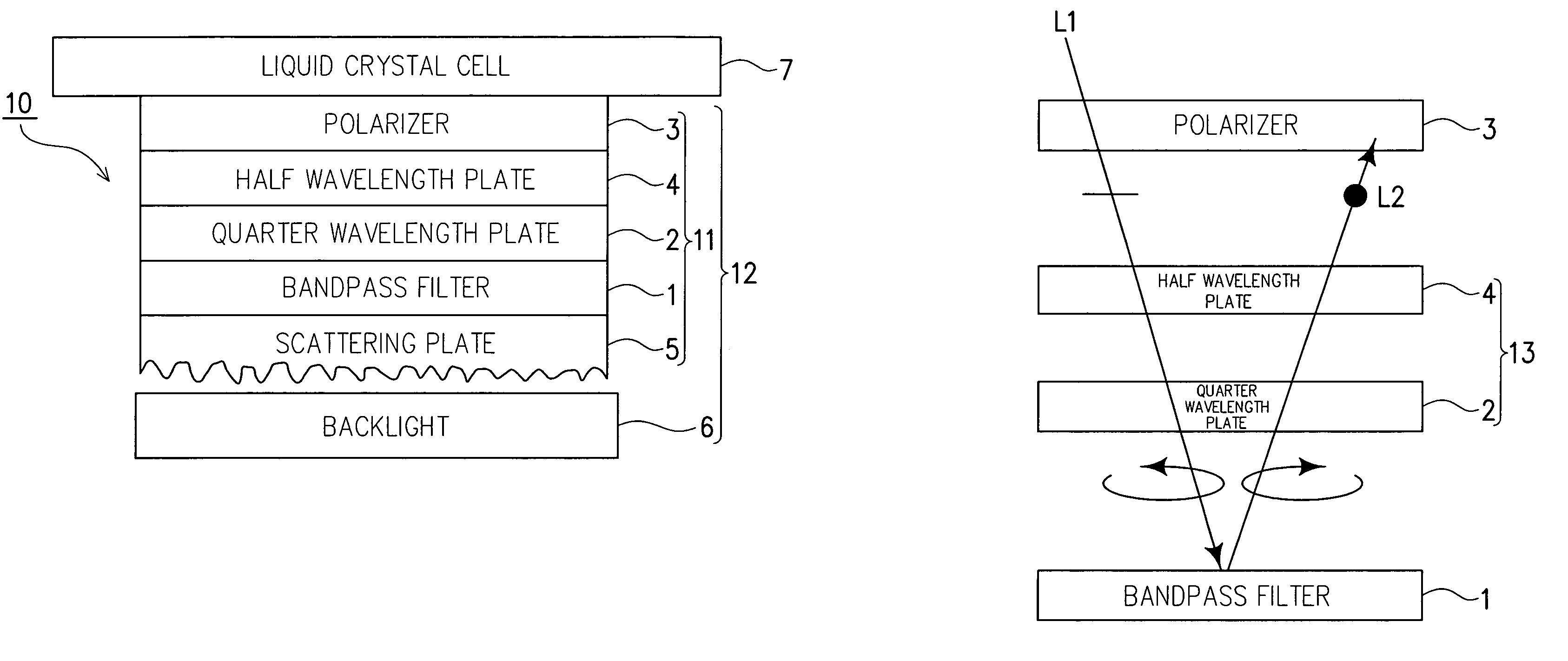
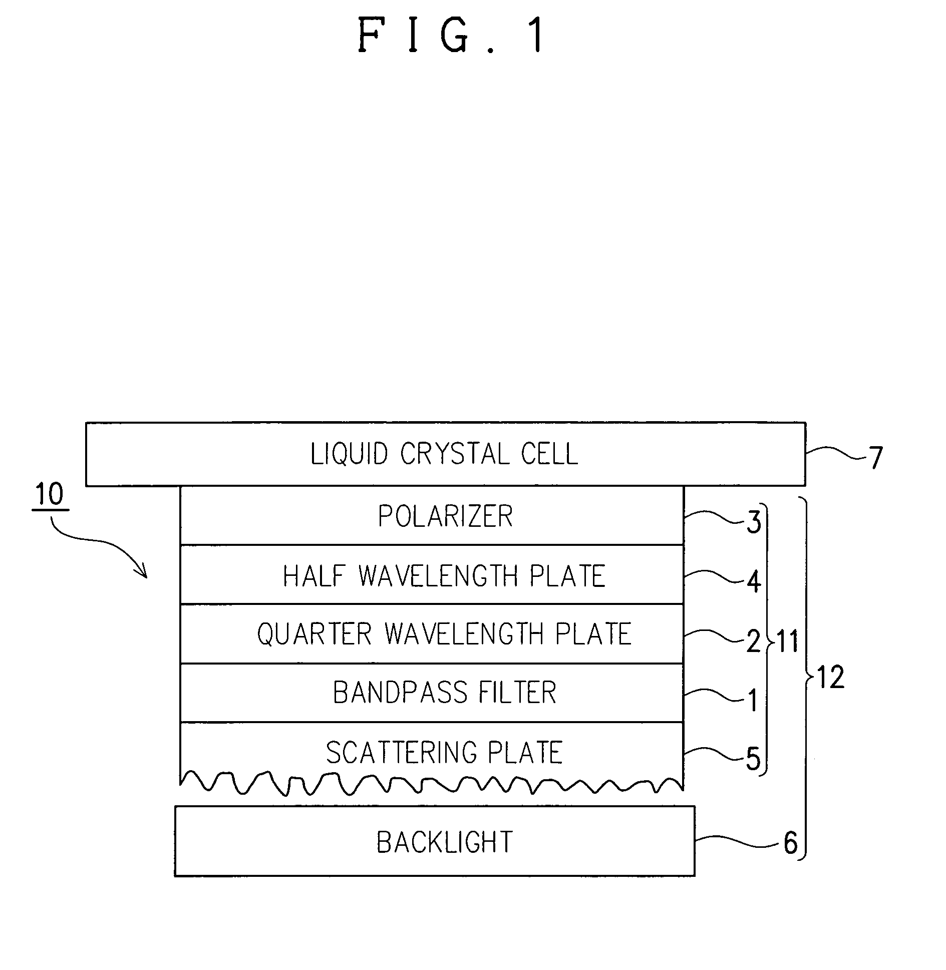
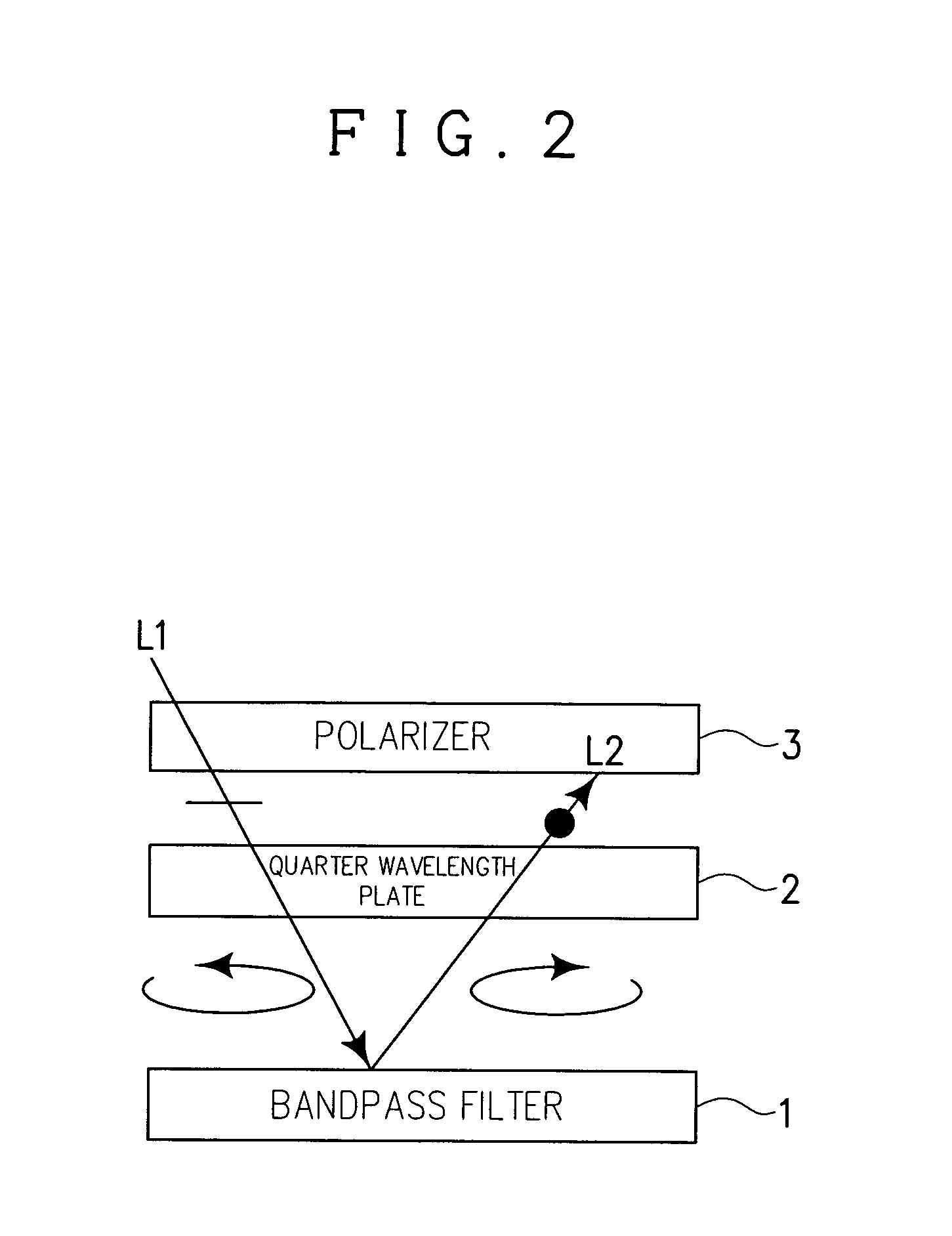
[0077]The bandpass filter of this example reflects light having a wavelength other than a wavelength of around 545 nm. Accordingly, where this bandpass filter is located between a polarizer fixed on the side of the backlight of the liquid crystal cell and the backlight, external light incident f...

example 2

[0080]Twenty thin films of a dielectric material made of ZrO2 / SiO2 were laminated together so as to prepare a short-wavelength pass bandpass filter (dichroic color filter) having a half wavelength value of 580 nm, as illustrated in FIG. 5(a). As a substrate, which serves as a base for lamination, a glass plate having a thickness of 0.4 mm was used.

[0081]A backlight with a single-color emission cold cathode lamp as a light source having the maximum of an emission line spectrum at a wavelength of 545 nm was located as opposed to the dichroic color filter, as illustrated in FIG. 5(a).

[0082]As in this example, where an emission spectrum of the backlight is limited to a single, specific wavelength (545 nm), and the reflection band of the dichroic color filter is limited to the long wavelength side, the reflection color of the dichroic color filter is colored. Therefore, it is possible to produce a sufficient reflection prevention effect by effecting reflection prevention mainly for a wav...

example 3

[0085]Twenty-one thin films of TiO2 / SiO2 were laminated together by vapor deposition so as to prepare a bandpass filter (interference filter) exhibiting a high transmittance for three wavelengths of an emission spectrum of a three-band cold cathode lamp, while reflecting different wavelengths of light, as illustrated in FIG. 6(a). As a substrate, which serves as a base for lamination, a PET film (LUMIRROR manufactured by Toray Industries, Inc. thickness: 75 μm) was used.

[0086]With the above bandpass filter, there was exhibited a light condensing characteristics that light emitted from a backlight with the three-band cold cathode lamp as a light source is reflected when it is out of an incident angle range of about ±20 degrees relative to the perpendicular direction, and returned towards the backlight.

[0087]As in this example, where a bandpass filter, which allows three wavelengths of light to pass through and reflects different wavelengths of light, is to be used, it is necessary to...


PUM


Abstract

An optical element 11 includes a bandpass filter made of a lamination of thin films respectively having different refraction factors so as to selectively allow light emitted from a backlight 6 to pass therethrough, and a polarizer 3, a quarter-wavelength plate 2 located between the bandpass filter 6 and the polarizer 3 so as to prevent light incident from the side of the polarizer 3 from being reflected by the bandpass filter 1 and then emitted from the side of the polarizer 3.

Description

FIELD OF THE INVENTION[0001]This invention relates to an optical element of a bandpass-filter-type, which is capable of forming a surface light source device having an excellent forward directivity, which is suitable for use in a liquid crystal display, and more particularly to an optical element, which prevents reflection of light, which has been emitted from a liquid crystal cell and reached a surface of a bandpass filter, from being visually recognized, thereby enabling limiting deterioration in display quality of a liquid crystal display.BACKGROUND OF THE INVENTION[0002]A surface light source device such as an EL (Electric Luminescence) backlight, CCFL (Cold Cathode Fluorescent Lamp) backlight, and LED (Light Emitting Diode) backlight used in a liquid crystal display usually has a peak at a certain wavelength.[0003]Accordingly, by arranging a bandpass filter (interference filter), which reflects a certain wavelength of light emitted from a backlight in case of oblique incident l...

Claims


Application Information

Patent Timeline
IPC IPC(8): G02F1/1335G02B5/28
CPCG02B5/285G02B5/287
Inventor HARA, KAZUTAKA
Owner NITTO DENKO CORP
Why Eureka
Try Eureka