Medical Pendant System

a technology of medical accessories and pendants, applied in the field of medical accessories, can solve the problems of inconvenient positioning adjustment, inconvenient maintenance, and invariability, and achieve the effect of free adjustment of the position of the medical accessory and easy disassembly

Active Publication Date: 2016-05-26
MAQUET SUZHOU
View PDF2 Cites 0 Cited by
  • Summary
  • Abstract
  • Description
  • Claims
  • Application Information

AI Technical Summary

Benefits of technology

[0037]According to the technical solution described above, the medical pendant system of the present invention can have the following beneficial technical effects: it can possess a standardized electrical interface, without complicatedly connecting electrical cables, disassembly is easy, and the free adjustment of the position of a medical attachment is allowed.

Problems solved by technology

Disadvantages of such technical solutions are: the location adjustment is not convenient for the users; there are too many cables, the space occupancy is relatively high, and the length of the cables is fixed; there are no extended functions; the maintenance is not convenient; and there are too many main control circuit boards, leading not versatile.

Method used


Image

  • Medical Pendant System
  • Medical Pendant System
  • Medical Pendant System

Examples


Embodiment Construction

[0077]The present invention is further described in connection with drawings and particular embodiments as follows and elaborated in more detail in the following description in order to fully understand the present invention, but it is evident that the present invention can be implemented in many other ways which are different from those described herein; generalization and deduction can be made by a skilled in the art without departing from the connotation of the invention according to practical application, and therefore the protective scope of the present invention should not be limited by the specific content of embodiments of the present invention herein.

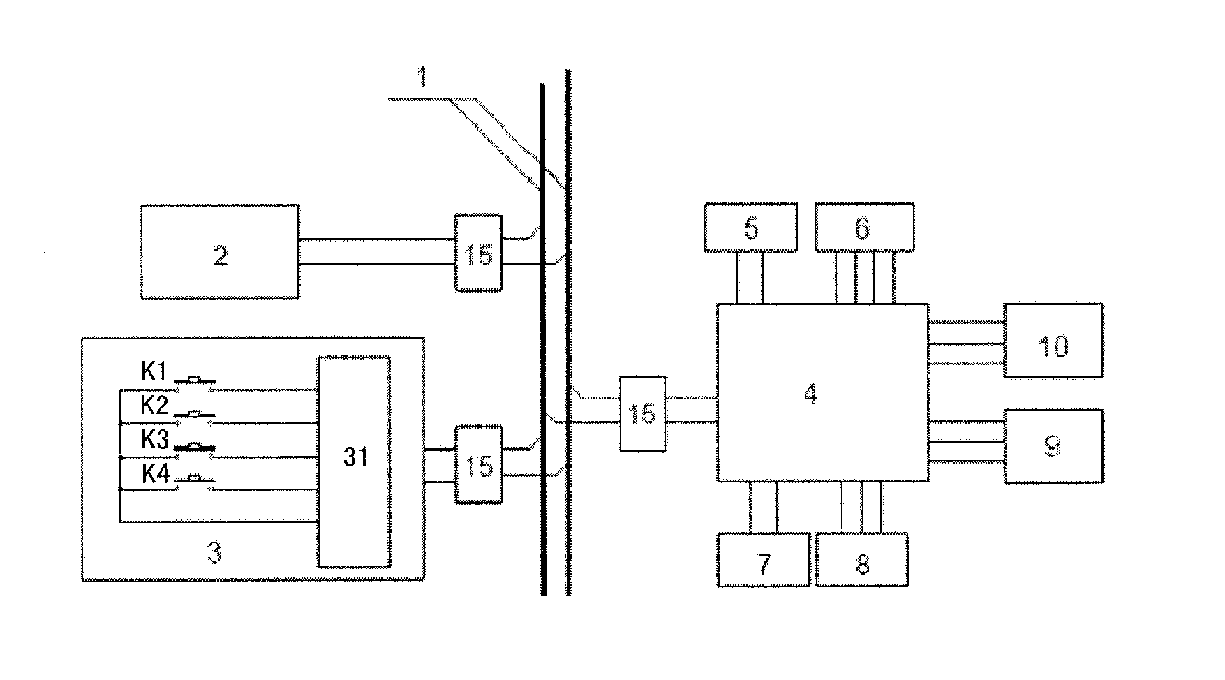
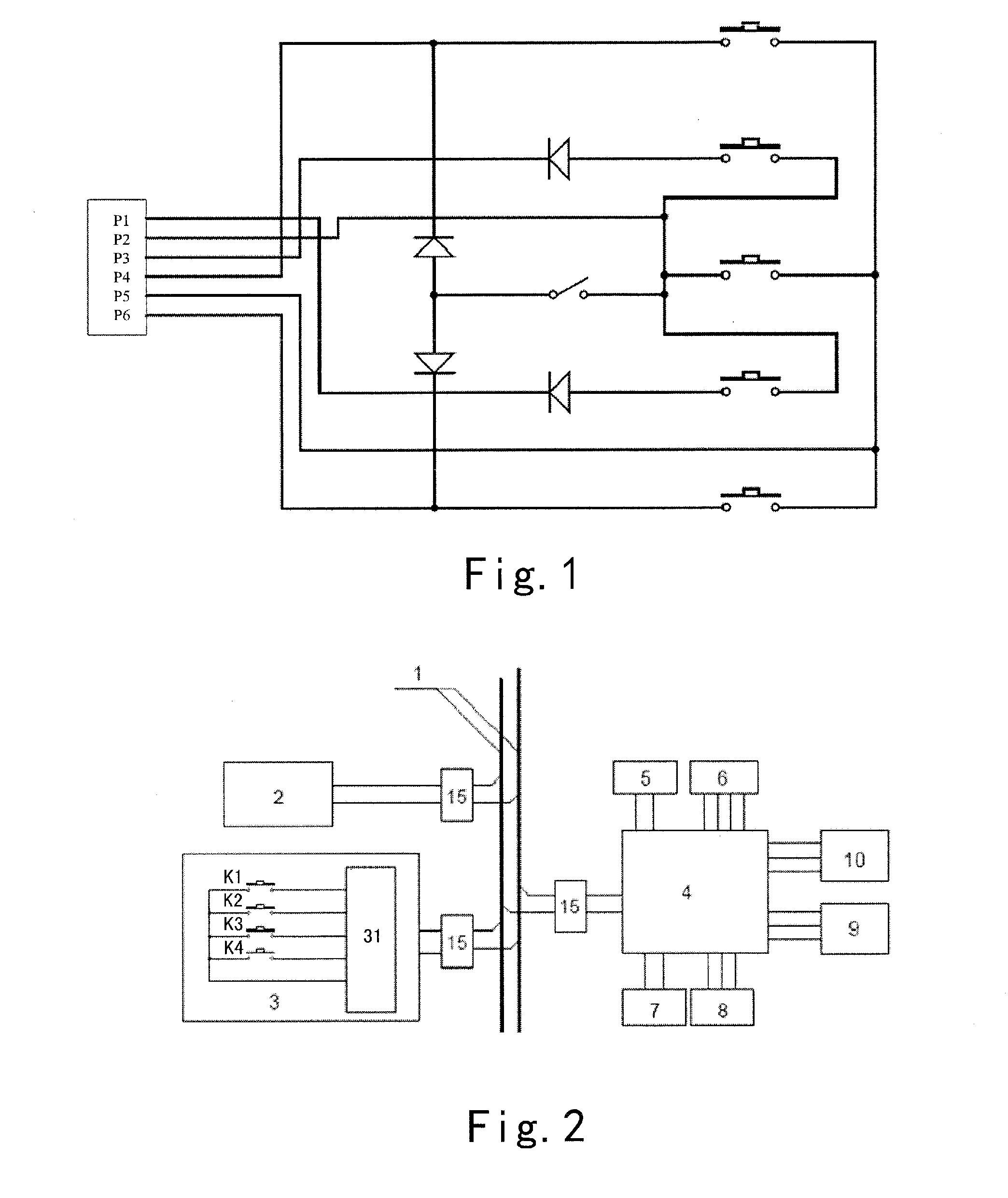
[0078]FIG. 2 shows a line diagram for the medical pendant system of an embodiment of the present invention.

[0079]The medical pendant system of the present invention comprises a movable component, an execution component and a bus 1; the movable component comprises a key control module 3; the key control module 3 comprises a brak...


PUM

PropertyMeasurementUnit
heightaaaaaaaaaa
mechanicalaaaaaaaaaa
lengthaaaaaaaaaa

Abstract

A medical pendant system, comprising. a movable component, an execution component and a bus (1); the movable component comprises a key control module (3); the key control module (3) comprises a braking system control key (K1, K4) and a pendant lifting/lowering control key (K2, K3); the execution component comprises an output control part (4), the output control part (4) being connected respectively with a bus power supply (5), a pendant motor (9) and a braking system (10); the movable component and the execution component are connected respectively to the bus (1); the bus (1) is used for transmitting power supply and also for transmitting instructions from the movable component to the execution component. In the vertical direction the medical pendant system can be adjusted steplessly without having to alter the lengths of the cables. The number of cable cores is reduced, circuit design is optimized, installation and maintenance are easy, functional integration and extension are convenient, and reliability is improved.

Description

[0001]The present application claims the priorities of Chinese patent application No. 201310242880.9 filed on Jun. 19, 2013 and Chinese patent application No. 201410181033.0 filed on Apr. 30, 2014.TECHNICAL FIELD[0002]The present invention relates to the technical field of medical equipment, and more particularly to a medical pendant system.BACKGROUND ART[0003]Medical pendant system is an indispensable medical equipment used in modern hospital operating room, intensive care unit and the like. The current medical pendant systems mainly employ the following technical solutions: the circuit control part is connected in a fixed position manner; the line control part is connected in one-to-one manner; the number of several control keys corresponding to the number of several loops, see FIG. 1; and different main control circuits corresponding to different applications.[0004]Disadvantages of such technical solutions are: the location adjustment is not convenient for the users; there are to...

Claims


Application Information

Patent Timeline
Patent Type & Authority Applications(United States)
IPC IPC(8): A61B5/024A61B5/00H01H47/00
CPCA61B5/02438A61B5/6802A61B5/742H01H47/00A61G12/002E04F17/08
Inventor ZHAN, SHENGPINGZHANG, WEIHUANG, JIASHENGLI, QUNHUAJI, MING
Owner MAQUET SUZHOU
Why Eureka
Try Eureka