System and method for monitoring and controlling wind turbine blade deflection

a technology for wind turbines and blades, applied in the field of wind turbines, can solve the problems of increasing the risk of turbine blades striking the tower, fatigue of turbine blades and other components, and the deflection force of longer turbine blades, so as to reduce the probability of a rotor blade tower strike, and increase the probability of a rotor blade deflection

Active Publication Date: 2016-05-26
GENERAL ELECTRIC CO
View PDF5 Cites 25 Cited by
  • Summary
  • Abstract
  • Description
  • Claims
  • Application Information

AI Technical Summary

Benefits of technology

[0007]In one aspect, the present subject matter provides a unique system for monitoring and controlling the deflection of rotor blades of a wind turbine. The method includes operating the wind turbine at standard pitch angle settings for the rotor blades. Another step includes monitoring a loading condition of the wind turbine over a predetermined time period. A further step includes tracking a number of wind condition deviations of a certain magnitude occurring during a predetermined time period. The method also include altering one or more of the standard pitch settings of the rotor blades in response to the number of wind condition deviations exceeding a wind deviation threshold and/or the loading condition exceeding a loading threshold as an exceedance above the wind deviation threshold and the loading threshold indicates an increased probability of a rotor blade deflection occurring in one or more of the rotor blades. In addition, the method includes performing one or more additional corrective actions so as to reduce the probability of a rotor blade tower strike.
[0008]In another aspect, the present di

Problems solved by technology

Thus, longer turbine blades may be subject to increased deflection forces, particularly when a wind turbine is operating in high-load conditions.
This increased deflection can produce fatigue on the turbine blades and other components and can also increase the risk of the turbine blades striking the tower.
A tower strike can sig

Method used


Image

  • System and method for monitoring and controlling wind turbine blade deflection
  • System and method for monitoring and controlling wind turbine blade deflection
  • System and method for monitoring and controlling wind turbine blade deflection

Examples


Embodiment Construction

[0023]Reference now will be made in detail to embodiments of the present subject matter, one or more examples of which are illustrated in the drawings. Each example is provided by way of explanation, not limitation of the present subject matter. In fact, it will be apparent to those skilled in the art that various modifications and variations can be made in the present subject matter without departing from the scope or spirit of the present subject matter. For instance, features illustrated or described as part of one embodiment can be used with another embodiment to yield a still further embodiment. Thus, it is intended that the present subject matter covers such modifications and variations as come within the scope of the appended claims and their equivalents.

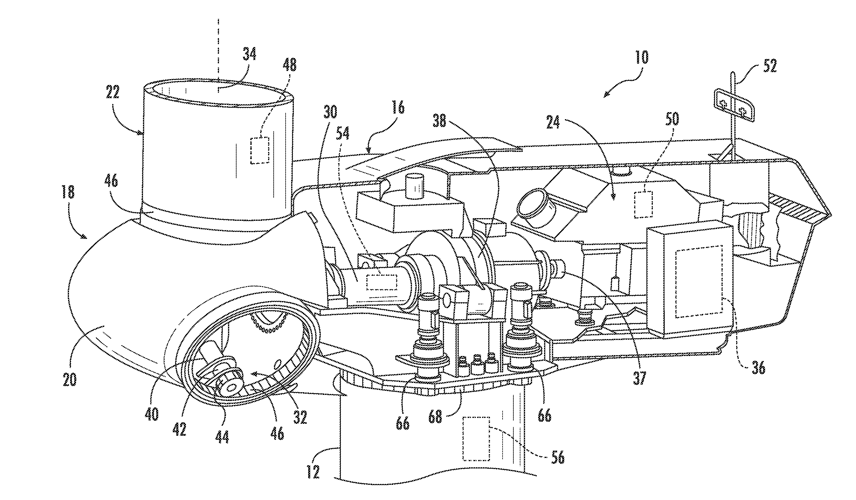
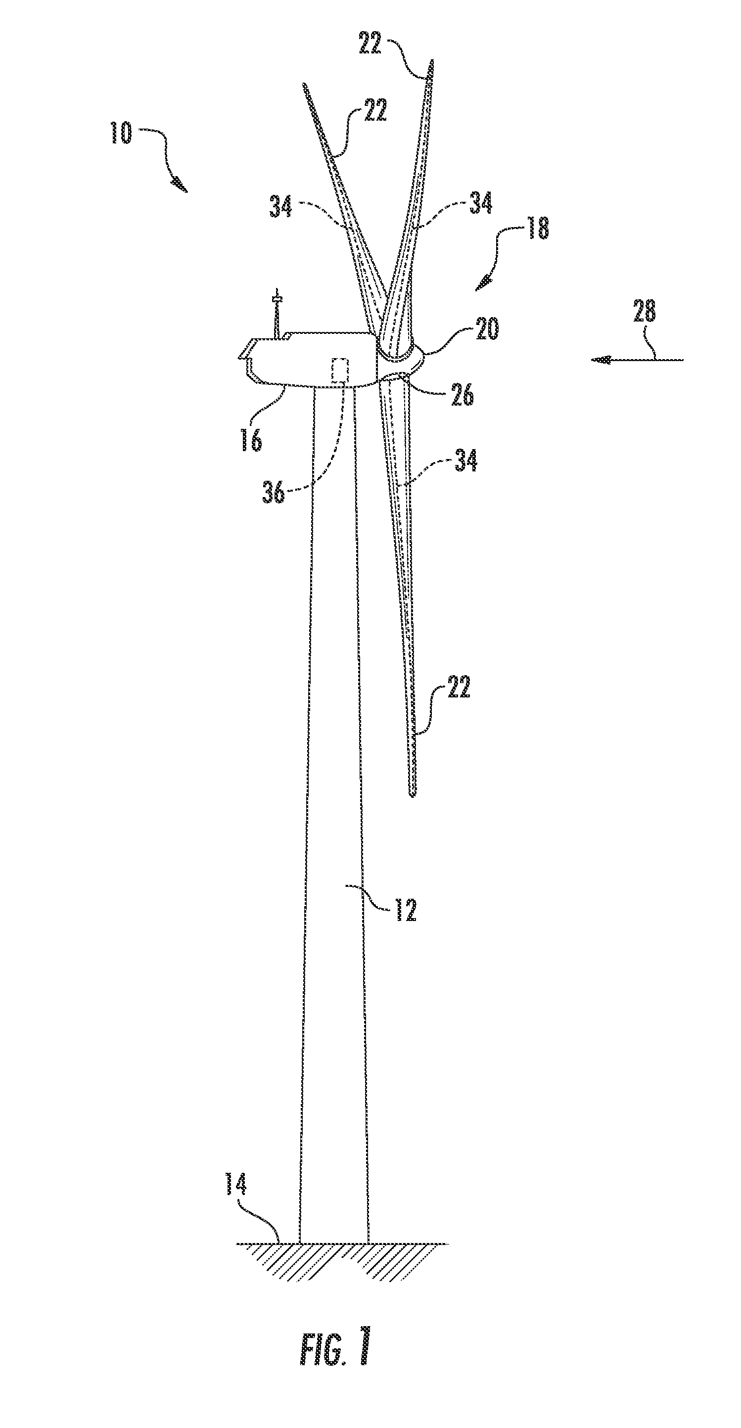
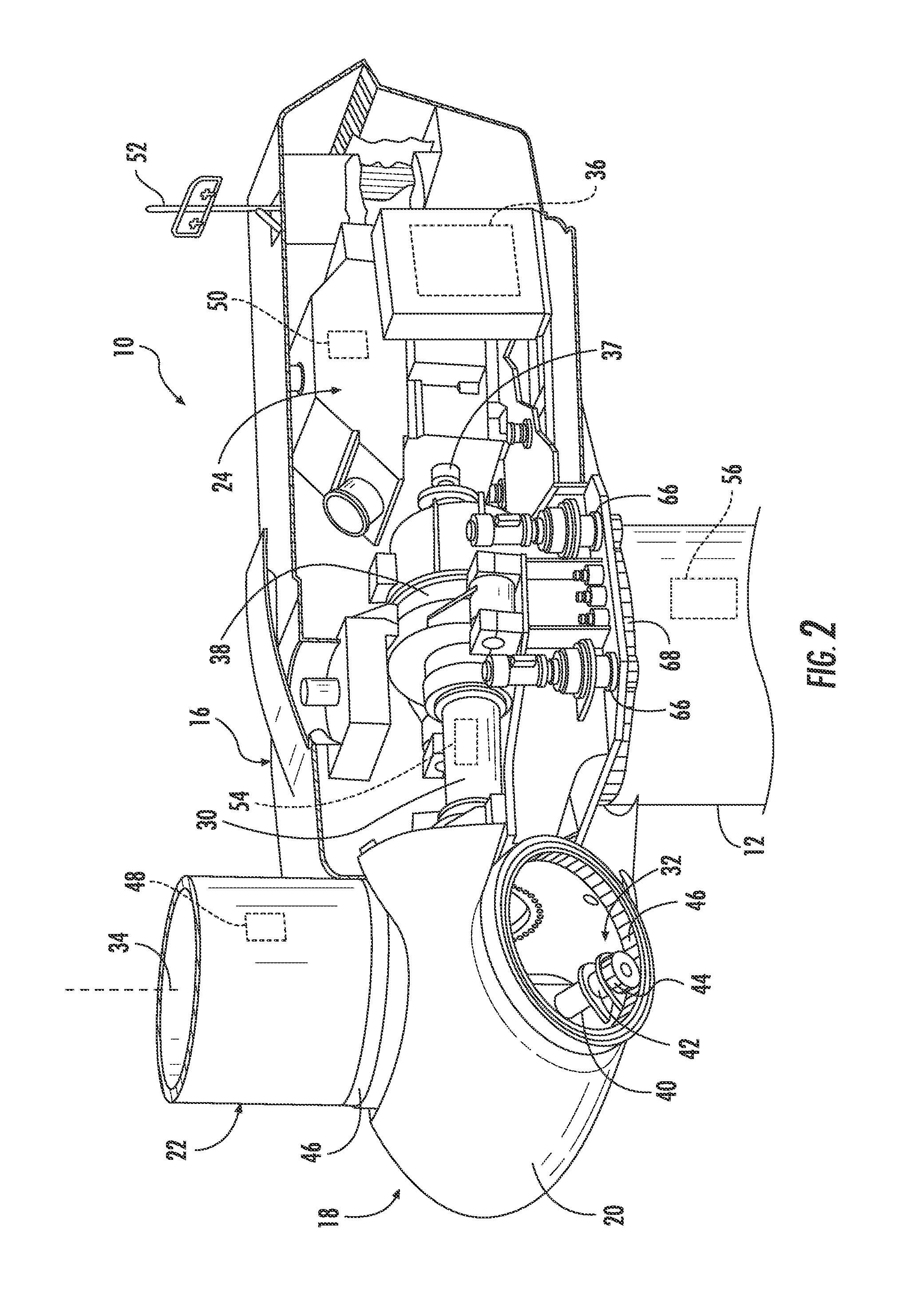
[0024]Generally, the present disclosure provides a unique system for monitoring and controlling the deflection of rotor blades of a wind turbine to reduce risk during conditions believed to be associated with blade tower stri...


PUM


Abstract

A system and method for monitoring and controlling the deflection of rotor blades of a wind turbine so as to prevent tower strikes is disclosed. The method includes operating the wind turbine at standard pitch angle settings. Another step includes monitoring a loading condition of the wind turbine over a predetermined time period. A further step includes tracking a number of wind condition deviations of a certain magnitude occurring during a predetermined time period. The method also include altering one or more of the standard pitch settings of the rotor blades in response to the number of wind condition deviations exceeding a wind deviation threshold and/or the loading condition exceeding a loading threshold as an exceedance indicates an increased probability of rotor blade deflection. The method further includes performing one or more additional corrective actions so as to reduce the probability of a rotor blade tower strike.

Description

FIELD OF THE INVENTION[0001]The present subject matter relates generally to wind turbines and particularly to turbine blade deflection. More particularly, the present subject matter relates to systems and methods for monitoring and controlling turbine blade deflection during operation of a wind turbine.BACKGROUND OF THE INVENTION[0002]Wind power is considered one of the cleanest, most environmentally friendly energy sources presently available, and wind turbines have gained increased attention in this regard. A modern wind turbine typically includes a tower, a generator, a gearbox, a nacelle, and one or more turbine blades. The turbine blades capture kinetic energy from wind using known foil principles and transmit the kinetic energy through rotational energy to turn a shaft coupling the rotor blades to a gearbox, or if a gearbox is not used, directly to the generator. The generator then converts the mechanical energy to electrical energy that may be deployed to a utility grid.[0003...

Claims


Application Information

Patent Timeline
IPC IPC(8): F03D7/02F03D7/04
CPCF03D7/0288F03D7/047F03D7/0224F05B2270/17F05B2270/32F05B2270/322F05B2270/331F03D17/00Y02E10/72
Inventor COOK, MARK LEESCHUELL, NADINE
Owner GENERAL ELECTRIC CO
Why Eureka
Try Eureka