Sheath member
- Summary
- Abstract
- Description
- Claims
- Application Information
AI Technical Summary
Benefits of technology
Problems solved by technology
Method used
Image


Examples
first embodiment
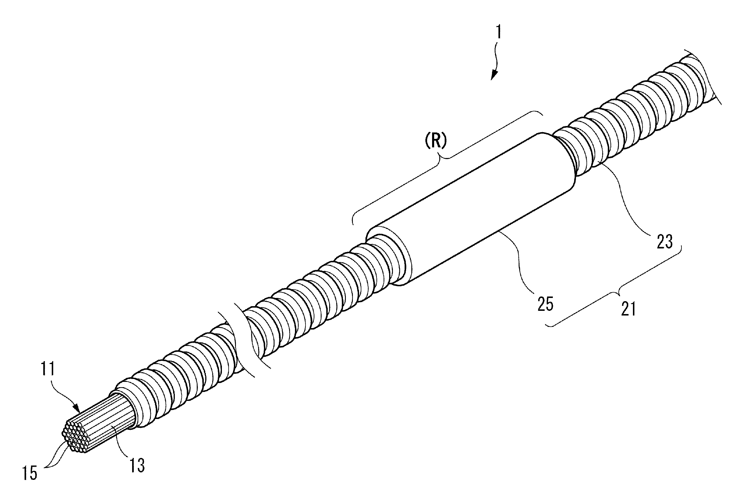
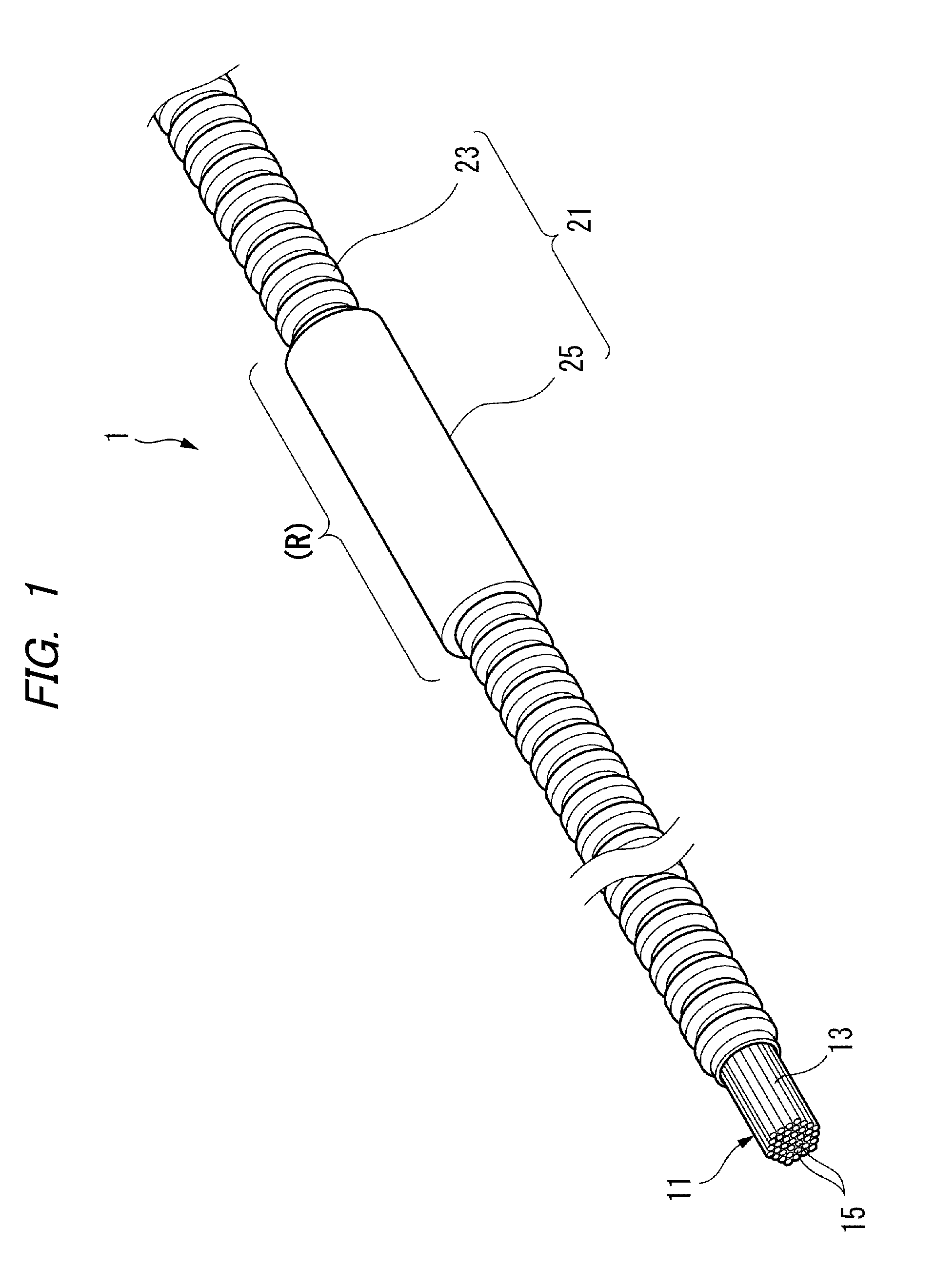
[0033]As shown in FIG. 1, a wire harness 1 has an electric wire bundle 11 in which a plurality of electric wires 15 are collected in a bundle form and a sheath member 21 covering part of the electric wire bundle 11 in the longitudinal direction thereof.
[0034]The electric wire bundle 11 is configured such that the electric wires 15, each having a conductive core wire (not shown) and an insulating coating 13 made of a synthetic resin and covering the outer periphery of the core wire, are collected in a bundle form. The electric wire bundle 11 is bundled with an adhesive tape, such as a wire harness tape (not shown). However, the electric wire bundle 11 may be configured such that the plurality of electric wires 15 are twisted and collected in a bundle form. Furthermore, a single electric wire may be used instead of the electric wire bundle 11.
[0035]As shown in FIGS. 2 and 3, the sheath member 21 includes a flexible and cylindrical main body 23 and a deformation restricting portion 25...
second embodiment
[0047]As shown in FIG. 6, the sheath member 21B is provided with the deformation restricting portions 25B at the bent sections 24 of the main body 23. In other words, the shape maintaining range (R) includes the bent sections 24. Hence, the deformation at the bent sections 24 of the main body 23 is restricted. In other words, a case in which the main body 23 is required to be maintained in a bent shape in the shape maintaining range (R) is assumed in the The wire harness can be routed in a desired routing shape by holding the electric wire bundle 11 inside the sheath member 21B. There can be a case in which it is preferable that the deformation at the bent sections 24 of the main body 23 is restricted depending on the routing state of the wire harness.
[0048]The sheath member 21B having the configuration described above can be produced by bending the main body 23 having the same straight line shape as that of the main body 23 for use in producing the sheath member 21 according to th...
third embodiment
[0052]With the sheath member 21C the outer shape of the deformation restricting portion 25C corresponds to the shape of the mounting surface 81, the contacting object that is brought into contact with the sheath member 21C, whereby wobbling and flapping can be prevented after the routing of the wire harness. In other words, in the conventional fastening method using a corrugated tube being circular in cross section, the wire harness is not held stably and wobbling and flapping may occur after the routing of the wire harness as described above. If wobbling and flapping occur, noise may be generated or breakage due to fatigue may be caused. On the other hand, with the sheath member 21C, the sheath member 21C is routed along the contacting object such that it is firmly attached to the contacting object, whereby the force for holding the wire harness is increased and wobbling and flapping can be prevented.
[0053]A sheath member 21D according to a fourth embodiment of the present inventi...
PUM
| Property | Measurement | Unit |
|---|---|---|
| Thickness | aaaaa | aaaaa |
| Flexibility | aaaaa | aaaaa |
| Shape | aaaaa | aaaaa |
Abstract
Description
Claims
Application Information
 - R&D Engineer
- R&D Manager
- IP Professional
- Industry Leading Data Capabilities
- Powerful AI technology
- Patent DNA Extraction
Browse by: Latest US Patents, China's latest patents, Technical Efficacy Thesaurus, Application Domain, Technology Topic.
© 2024 PatSnap. All rights reserved.Legal|Privacy policy|Modern Slavery Act Transparency Statement|Sitemap