Device and method for aligning substrates

a technology of substrates and devices, applied in the direction of electrical devices, sawing equipment, instruments, etc., can solve problems such as positioning faults

Active Publication Date: 2016-05-26
EV GRP E THALLNER GMBH
View PDF0 Cites 18 Cited by
  • Summary
  • Abstract
  • Description
  • Claims
  • Application Information

AI Technical Summary

Benefits of technology

[0063]The advantage of the invention lies mainly in that the device can also be operated in a vacuum. Due to the travel paths of the upper and / or lower mount and thus of the first (lower) and / or second (upper) substrate, which paths are comparatively short, mechanical components for carriages / bearings / stepping motors which are vacuum-suitable can be used. Thus it is possible for the first time to install a bond module and an alignment module in a vacuum cluster, preferably a high vacuum cluster, and to transport the substrate from the alignment module to the bond module within a region which can be evacuated without exposing the substrate again to an atmosphere.
[0064]Another advantage lies in the possibility of using visible light. The use of transmission techniques can be abandoned. Furthermore all substrates, even substrates which are opaque to the wide range of the electromagnetic spectrum, can be measured since the alignment markings can be found on the surfaces without having to transilluminate the substrate.
[0065]In all figures the adjustment units are always shown within the housing. Of course it would also be conceivable for the adjustment units to be located outside the housing and by corresponding vacuum penetrations to control the sample holders which are located within the housing. The same also applies to the detection means. In the optimum embodiment which is however of course technically difficult to implement, only the two substrates which are to be aligned to one another would be located in vacuum.
[0076]In one special embodiment the substrates which have been aligned to one another in are clamped to one another with a method mentioned in patent PCT / EP2013 / 056620, to which reference is made. The clamping method uses small magnet bodies for prompt, efficient and easy fixing of the two substrates which are brought into contact and which are aligned to one another. The two substrates can also be prefixed via molecular forces. The clamping can also take place purely mechanically.
[0077]To the extent device features are disclosed here and in the following description of the figures they should also be considered disclosed as method features and vice versa.

Problems solved by technology

One special challenge in alignment technology is the face-to-face version.
This is not always the case for IR radiation and visible light.
One of the most serious technical problems is the positioning faults which arise by the movement of the substrates and which can occur especially in an environment which can be evacuated.

Method used


Image

  • Device and method for aligning substrates
  • Device and method for aligning substrates
  • Device and method for aligning substrates

Examples


Embodiment Construction

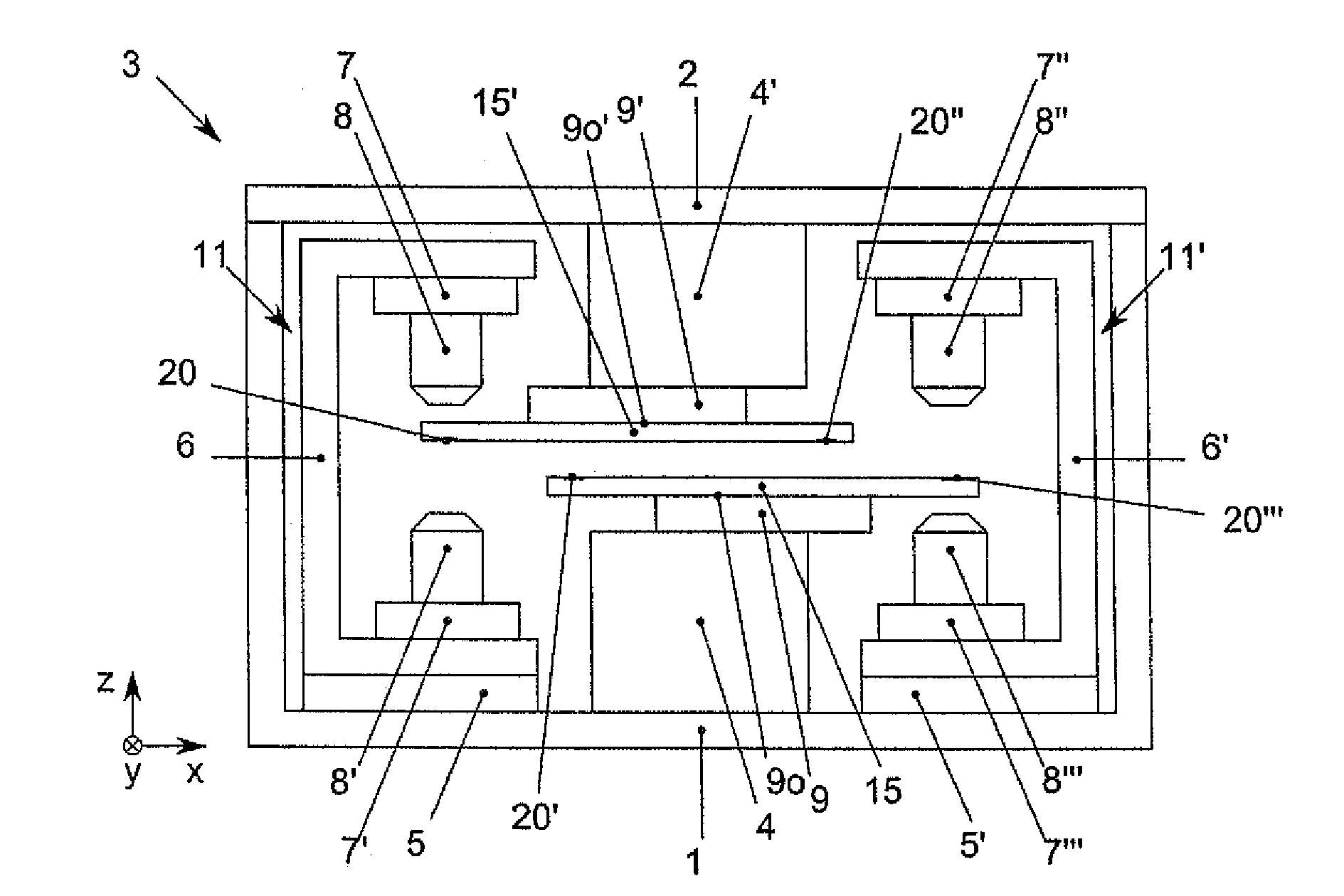
[0096]In the figures, advantages and features of the invention are labeled with reference numbers which identify them according to embodiments of the invention, components and features with the same function and / or a function with the same action being labeled with identical reference numbers.

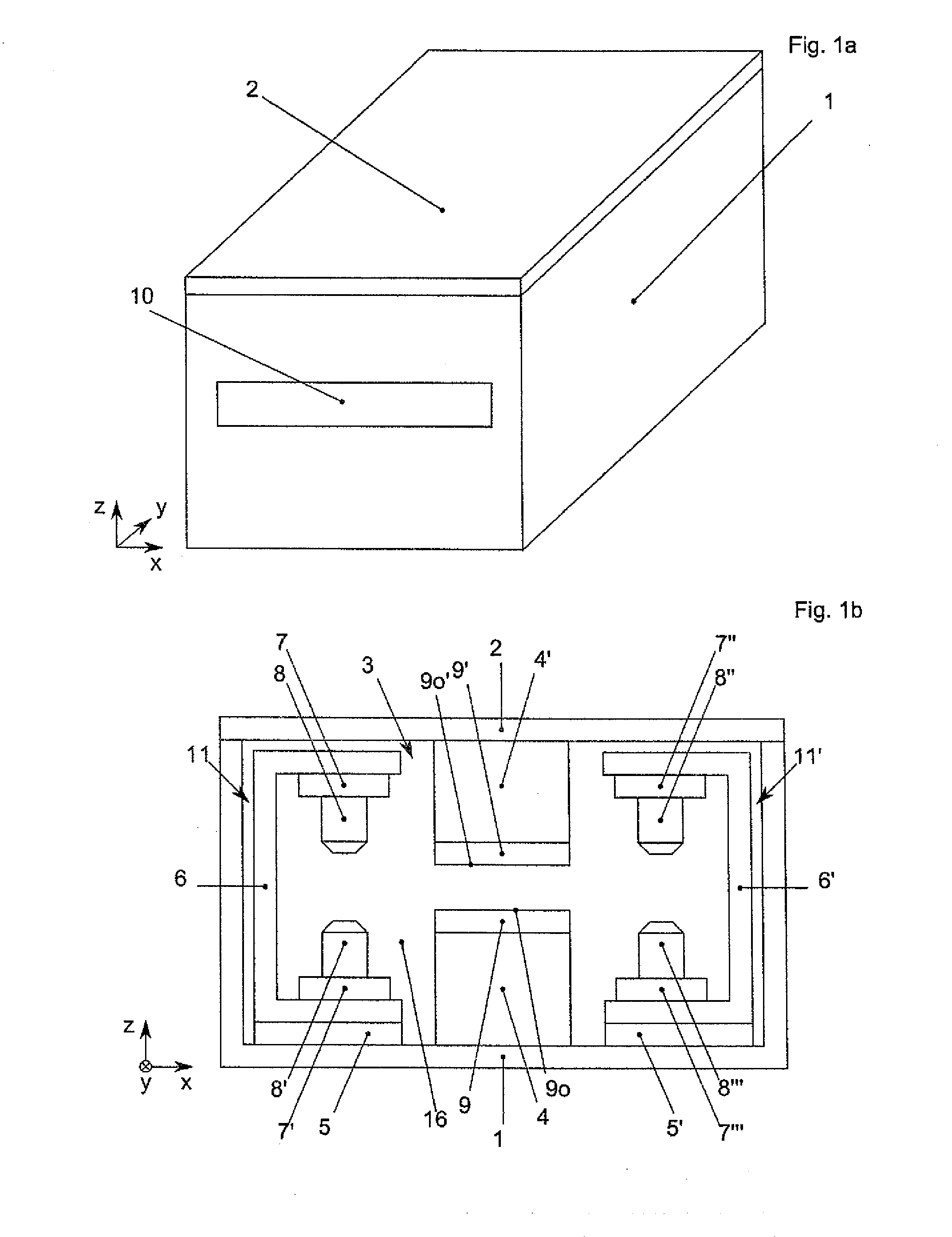
[0097]FIG. 1 shows one embodiment of the device of the invention. The components which are necessary for executing the method of the invention are located preferably in a vacuum-tight housing 1 which can be opened and closed vacuum-tight from one side via a cover 2. The loading and unloading of first substrates 15 and second substrates 15′ which are to be aligned to one another takes place preferably through a lock door 10. The lock door 10 is vacuum-tight and separates an interior 16 which is formed by the housing 1 and the cover 2 from the surrounding atmosphere.

[0098]If different pressure conditions should prevail between the interior 16 and the surrounding atmosphere, a lock (not shown) can...


PUM


Abstract

A method for alignment and contact-making of a first substrate with a second substrate using several detection units as well as a corresponding device.

Description

FIELD OF THE INVENTION[0001]This invention relates to a method for alignment and contact-making of a first substrate with a second substrate and a corresponding device.BACKGROUND OF THE INVENTION[0002]In the semiconductor industry substrates have been joined to one another for years. It is generally necessary to align the substrates to one another before the actual joining process, bonding. The substrates are aligned to one another with alignment systems. The alignment systems are able to detect alignment marks on the substrates and to align the substrates to one another such that the alignment marks complement one another accordingly. In most cases the alignment marks are complementary to one another.[0003]In order to correctly align two substrates to one another, at least four alignment marks, two on each substrate, are necessary. The alignment marks are preferably as near as possible to the edge of the substrate in order to increase the alignment accuracy.[0004]In an alignment pr...

Claims


Application Information

Patent Timeline
Patent Type & Authority Applications(United States)
IPC IPC(8): H01L21/68H01L21/66B65G47/26H01L21/67
CPCH01L21/681B65G47/26H01L22/26H01L21/67092
Inventor THALLNER, ERICH
Owner EV GRP E THALLNER GMBH
Why Eureka
Try Eureka