Image coding apparatus, image coding method, and program, and image decoding apparatus, image decoding method and program

a lossless coding and image coding technology, applied in the field of image coding apparatus, image coding method, program, etc., can solve the problem of insufficient compression efficiency of lossless coding in hevc, and achieve the effect of prioritizing compression performan

Active Publication Date: 2016-05-26
CANON KK
View PDF4 Cites 8 Cited by
  • Summary
  • Abstract
  • Description
  • Claims
  • Application Information

AI Technical Summary

Benefits of technology

[0013]The present invention achieves coding and decoding which support both of a lossless coding process which prioritizes compatibility with a lossy coding process and a lossless coding process which prioritizes compression performance. As a result, switching may be performed between these lossless coding processes in accordance with the requirement for an application.

Problems solved by technology

Therefore, there arises a problem in that the compression efficiency of lossless coding in HEVC is not sufficiently high.

Method used


Image

  • Image coding apparatus, image coding method, and program, and image decoding apparatus, image decoding method and program
  • Image coding apparatus, image coding method, and program, and image decoding apparatus, image decoding method and program
  • Image coding apparatus, image coding method, and program, and image decoding apparatus, image decoding method and program

Examples


first embodiment

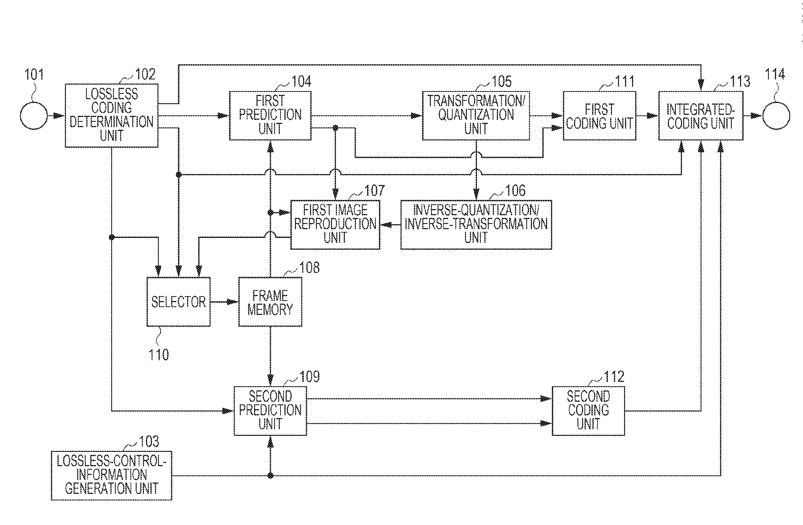
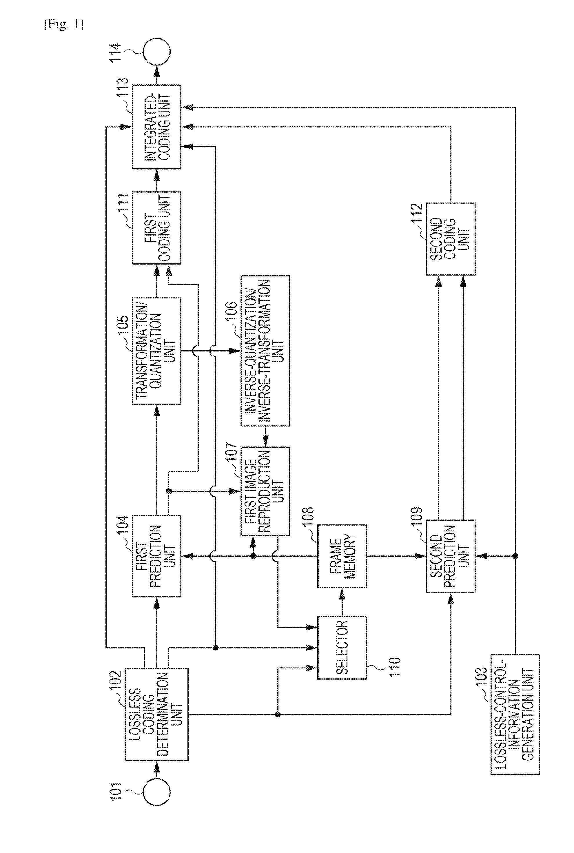
[0028]A first embodiment of the present invention will be described below by using the drawings. FIG. 1 is a block diagram illustrating an image coding apparatus according to the first embodiment. In FIG. 1, a terminal 101 is a terminal for inputting image data. A lossless coding determination unit 102 cuts out multiple blocks from the received image data, and determines whether reversible compression coding (hereinafter, referred to as lossless coding) or irreversible compression coding (hereinafter, lossy coding) is to be performed on each of the blocks. A lossless-control-information generation unit 103 generates and outputs lossless control information indicating what kind of intra prediction process is to be performed on a lossless coding block which is to be subjected to lossless coding.

[0029]A first prediction unit 104 performs, for example, intra prediction which is intra-frame prediction and inter prediction which is inter-frame prediction on each of the blocks of the image...

second embodiment

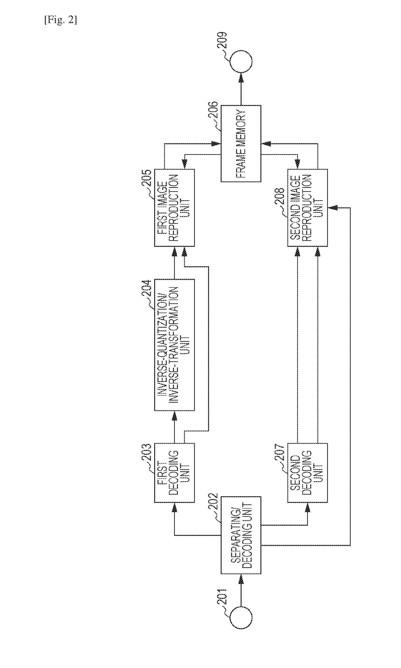
[0071]FIG. 2 is a block diagram illustrating the configuration of an image decoding apparatus according to a second embodiment of the present invention. The second embodiment will be described by taking an example in which coded data generated in the first embodiment is decoded. A terminal 201 is a terminal for inputting a coded bit stream.

[0072]A separating / decoding unit 202 separates information about the decoding process and coded data about coefficients from the bit stream, and decodes coded data which is present in the header of the bit stream. In the second embodiment, separating / decoding unit 202 reproduces the lossless control information and the lossless coding block information and outputs the lossless control information and the lossless coding block information to the subsequent stage. The separating / decoding unit 202 performs a reverse operation of that performed by the integrated-coding unit 113 in FIG. 1.

[0073]A first decoding unit 203 decodes the first coded data whi...

third embodiment

[0096]The processing units illustrated in FIGS. 1 and 2 are described as those constituted by using hardware, in the above-described embodiments. Alternatively, the processes performed by the processing units in FIGS. 1 and 2 may be performed by using computer programs.

[0097]FIG. 8 is a block diagram illustrating an exemplary hardware configuration of a computer which may be applied to the image coding apparatus and the image decoding apparatus according to the above-described embodiments.

[0098]A central processing unit (CPU) 801 controls the entire computer by using computer programs and data which are stored in a random-access memory (RAM) 802 and a read only memory (ROM) 803, and performs the processes which are described as those performed by the image processing apparatuses according to the above-described embodiments. That is, the CPU 801 functions as the processing units illustrated in FIGS. 1 and 2.

[0099]The RAM 802 has an area for temporarily storing computer programs and d...


PUM


Abstract

The present invention is made to enable switching between lossless coding which prioritizes compatibility with a lossy coding process and lossless coding which prioritizes compression performance.An image coding apparatus of the present invention includes the following configuration. The image coding apparatus which encodes an image on a block-by-block basis includes a first coding unit and a second coding unit. The first coding unit performs irreversible compression coding on a received first block. The second coding unit performs reversible compression coding on a received second block. The second coding unit encodes the second block by using either of a first intra prediction mode for performing intra prediction on a block-by-block basis and a second intra prediction mode for performing intra prediction on a pixel-by-pixel basis.

Description

TECHNICAL FIELD[0001]The present invention relates to an image coding apparatus, an image coding method, and a program, particularly to an intra prediction process performed on a lossless coding block.BACKGROUND ART[0002]A system, H.264 / MPEG-4 AVC (hereinafter, abbreviated as H.264), is known as a coding system for compressing and recording a movie (see NPL 1).[0003]In H.264, lossless coding may be performed by performing a transformation bypass process in which orthogonal transformation and quantization are bypassed. In particular, lossless coding has a characteristic in which, when intra prediction is performed in a horizontal or vertical direction, differential pulse-code modulation (DPCM) coding is performed. In DPCM coding, instead of normal prediction performed on the basis of coded pixels around a target pixel, prediction is performed on a pixel-by-pixel basis in a block.[0004]Recently, an activity for achieving an international standard for a higher-efficiency coding system ...

Claims


Application Information

Patent Timeline
Patent Type & Authority Applications(United States)
IPC IPC(8): H04N19/50H04N19/11H04N19/91H04N19/124H04N19/176H04N19/182H04N19/44H04N19/12
CPCH04N19/50H04N19/44H04N19/11H04N19/91H04N19/124H04N19/176H04N19/182H04N19/12H04N19/70H04N19/103H04N19/60H04N19/593
Inventor SHIMA, MASATO
Owner CANON KK
Why Eureka
Try Eureka