Thread production device

a production device and yarn technology, applied in the direction of lap forming devices, transportation and packaging, yarn, etc., can solve the problems of unstable twisting state generated by twisting means, insufficient strength of produced carbon nanotube yarn, etc., and achieve the effect of efficient twisting and sufficient strength

Active Publication Date: 2016-06-09
MURATA MASCH LTD
View PDF20 Cites 15 Cited by
  • Summary
  • Abstract
  • Description
  • Claims
  • Application Information

AI Technical Summary

Benefits of technology

[0019]In a yarn producing apparatus according to a preferred embodiment of the present invention, the twisting unit may include a wind driving mechanism that causes a winding shaft provided with a winding tube to rotate about the winding centerline of the winding shaft to wind the carbon nanotube yarn onto the winding tube, a twist driving mechanism that causes a guide to rotate around the winding tube to guide the carbon nanotube yarn to the winding tube, to twist the carbon nanotube fibers and produce the carbon nanotube yarn while causing the carbon nanotube fibers, carbon nanotube yarn, or both to swirl, and a traverse driving mechanism that causes the guide to reciprocate relative to the w

Problems solved by technology

As a result, a twisting state generated by the twisting means may become uns

Method used


Image

  • Thread production device
  • Thread production device
  • Thread production device

Examples


first preferred embodiment

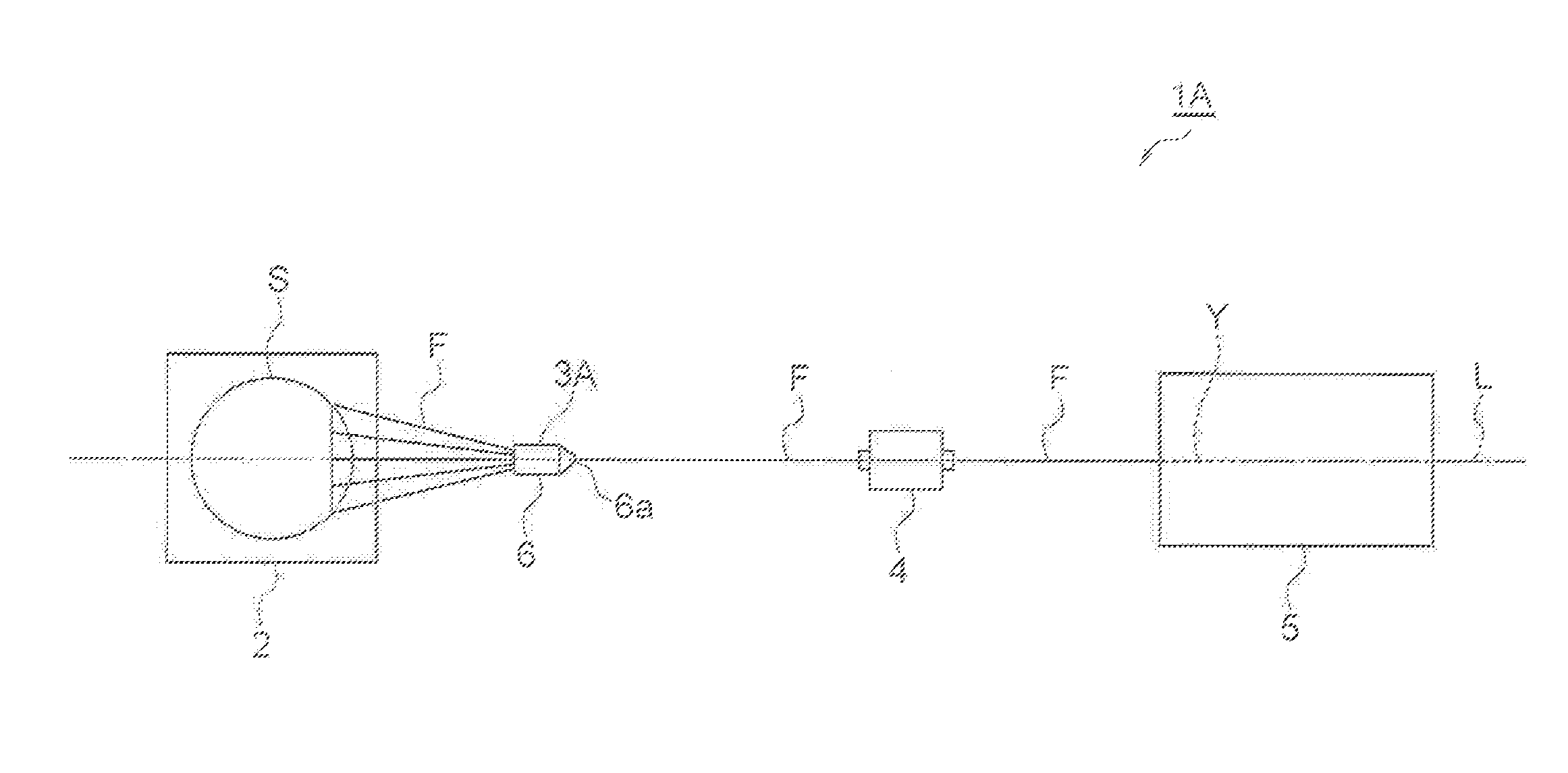
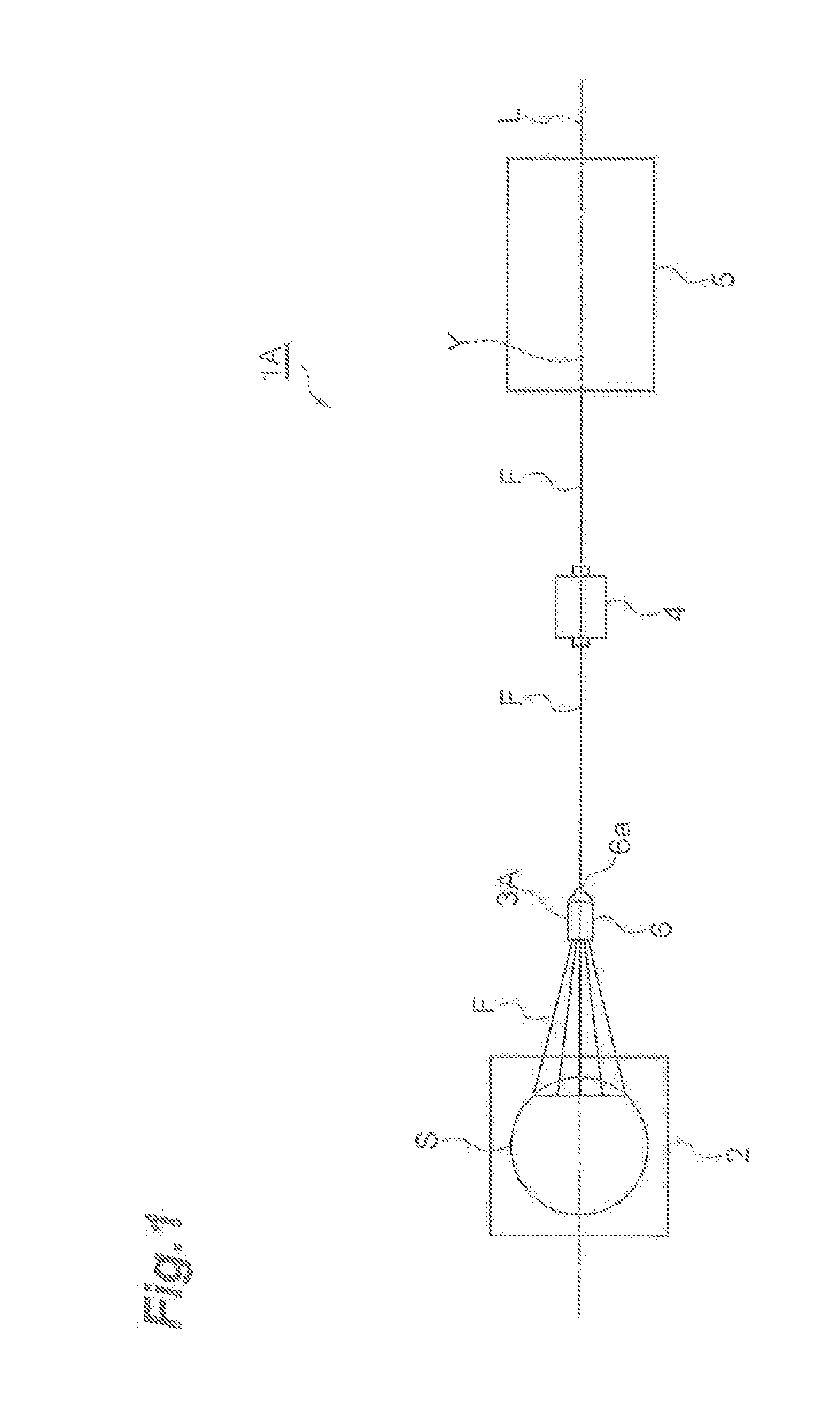
[0031]As shown in FIG. 1, a yarn producing apparatus 1A is an apparatus that produces carbon nanotube yarn (hereinafter referred to as “CNT yarn”) Y from carbon nanotube fibers (hereinafter referred to as “CNT fibers”) F while causing the CNT fibers F to run. The yarn producing apparatus 1A includes a substrate support 2, a preliminary aggregating unit 3A, a tensioning unit 4, and a twisting and winding device (twisting unit) 5. The substrate support 2, the preliminary aggregating unit 3A, the tensioning unit 4, and the twisting and winding device 5 are arranged in this order on a predetermined straight line L. The CNT fibers F run from the substrate support 2 toward the twisting and winding device 5. The CNT fibers F preferably are a set of a plurality of fiber threads (fibers) of carbon nanotube. The CNT yarn Y preferably is the twisted (genuine-twisted or false-twisted) CNT fibers F.

[0032]The substrate support 2 supports a carbon nanotube forming substrate (hereinafter referred t...

second preferred embodiment

[0046]As shown in FIG. 3, a yarn producing apparatus 1B mainly differs from the yarn producing apparatus 1A described above in that a preliminary aggregating unit 3B includes an adjusting mechanism 10. The preliminary aggregating unit 3B includes a plurality of first plate-shaped members 12 and a plurality of second plate-shaped members 13 as assembly parts that define a through hole 11 that the CNT fibers F pass through in contact with the through hole 11. The adjusting mechanism 10 adjusts the aggregation state of the CNT fibers F by adjusting the positional relation between the first plate-shaped members 12 and the second plate-shaped members 13 and adjusting the opening area of the through hole 11.

[0047]A plurality of (for example, two) first plate-shaped members 12 are attached at a predetermined distance from each other to the adjusting mechanism 10 on one side of the predetermined line L. A plurality of (for example, three) second plate-shaped members 13 are attached at a dis...


PUM

PropertyMeasurementUnit
Forceaaaaaaaaaa
Areaaaaaaaaaaa
Tensionaaaaaaaaaa

Abstract

A yarn producing apparatus is an apparatus for producing CNT (carbon nanotube) yarn from CNT fibers while causing the CNT fibers to run. The yarn producing apparatus includes an aggregating unit that aggregates the CNT fibers, and a twisting and winding device that twists the CNT fibers aggregated by the aggregating unit.

Description

BACKGROUND OF THE INVENTION[0001]1. Field of the Invention[0002]The present invention relates to a yarn producing apparatus for producing carbon nanotube yarn from carbon nanotube fibers while causing the carbon nanotube fibers to run.[0003]2. Description of the Related Art[0004]A known example of the yarn producing apparatus as described above includes holding means for aggregating carbon nanotube fibers pulled out from a carbon nanotube forming substrate and twisting means for twisting the carbon nanotube fibers aggregated by the holding means (see, for example, Japanese Patent Application Laid-Open Publication No. 2010-116632).[0005]Japanese Patent No. 3954967 (FIG. 4) discloses spinnerets or nozzles for creating alignment of the suspended nanotube arrays. The spinnerets or nozzles allow a significant increase in the intensity of the extensional flow in the nanotube suspension with an accompanying increase in the degree of carbon nanotube alignment.[0006]In the yarn producing app...

Claims


Application Information

Patent Timeline
IPC IPC(8): D02G3/16D01G99/00D01H1/115
CPCD02G3/16D01G99/00D01H1/115D10B2101/122B65H51/015B65H54/2896B65H2701/314D01H13/04D01H1/04
Inventor TAKASHIMA, HIROKI
Owner MURATA MASCH LTD
Why Eureka
Try Eureka