Thread production device

a production device and yarn technology, applied in the field of yarn producing equipment, can solve the problem that the performance of produced yarn is not sufficien

Active Publication Date: 2016-05-19
MURATA MASCH LTD
View PDF8 Cites 10 Cited by
  • Summary
  • Abstract
  • Description
  • Claims
  • Application Information

AI Technical Summary

Benefits of technology

[0006]Preferred embodiments of the present invention, therefore, provide a yarn producing apparatus capable of producing yarn with sufficient performance.
[0008]In this yarn producing apparatus, the guide that causes the yarn to traverse the winding tube is rotated around the winding tube, such that the fibers, yarn, or both swirl, the fibers are twisted, and the yarn is produced. Even when applied to fibers such as carbon nanotube fibers that have a relatively low load-bearing value and a relatively small mass, the fibers are twisted appropriately. The fibers, yarn, or both are twisted and a balloon (the fibers, yarn, or both expanding like a balloon under centrifugal force) is provided such that the balloon appropriately absorbs tension variations produced in relatively less elastic fibers such as carbon nanotube fibers, and the fibers are twisted efficiently. This yarn producing apparatus thus produces yarn with sufficient performance.
[0009]In a yarn producing apparatus according to a preferred embodiment of the present invention, the fibers maybe carbon nanotube fibers, and the yarn may be carbon nanotube yarn. The twist driving mechanism may twist the fibers and produce the yarn while forming a balloon by swirling the fibers, yarn, or both. Even when applied to carbon nanotube fibers having a relatively low load-bearing value and a relatively small mass, the unique structure described above produces carbon nanotube yarn with sufficient performance.
[0012]Preferred embodiments of the present invention provide a yarn producing apparatus capable of producing yarn with sufficient performance.

Problems solved by technology

When the apparatus illustrated in FIG. 1 of Japanese Patent Application Laid-Open Publication No. 2010-65339 is applied to such carbon nanotube fibers, the traveler for yarn guide disposed on the ring fails to be rotated appropriately, and, as a result, the produced yarn may not have sufficient performance.

Method used


Image

  • Thread production device
  • Thread production device
  • Thread production device

Examples


Embodiment Construction

[0016]Preferred embodiments of the present invention will be described in details below with reference to the figures. It should be noted that the same or corresponding elements or portions in the figures are denoted with the same reference signs and an overlapping description will be omitted.

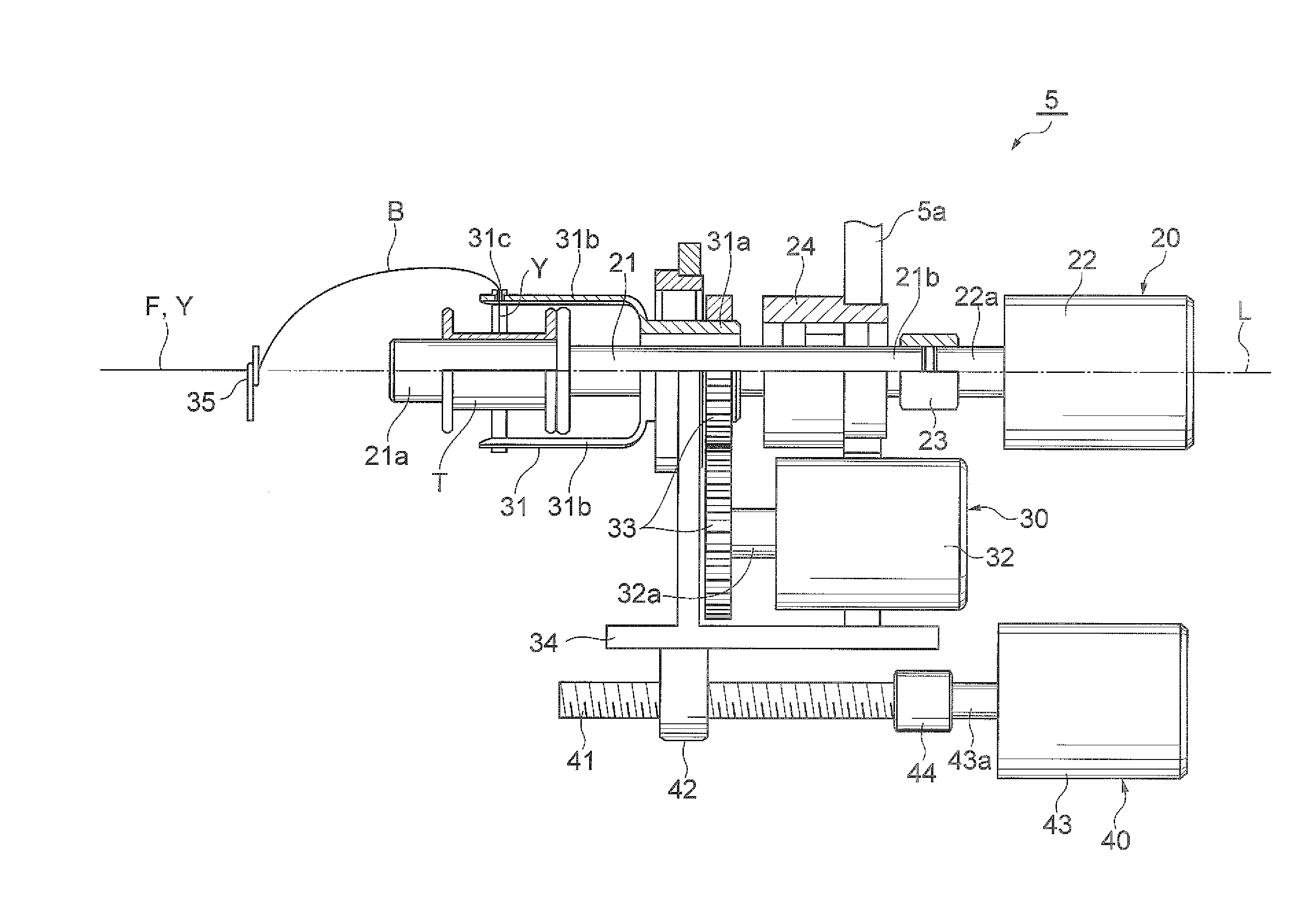
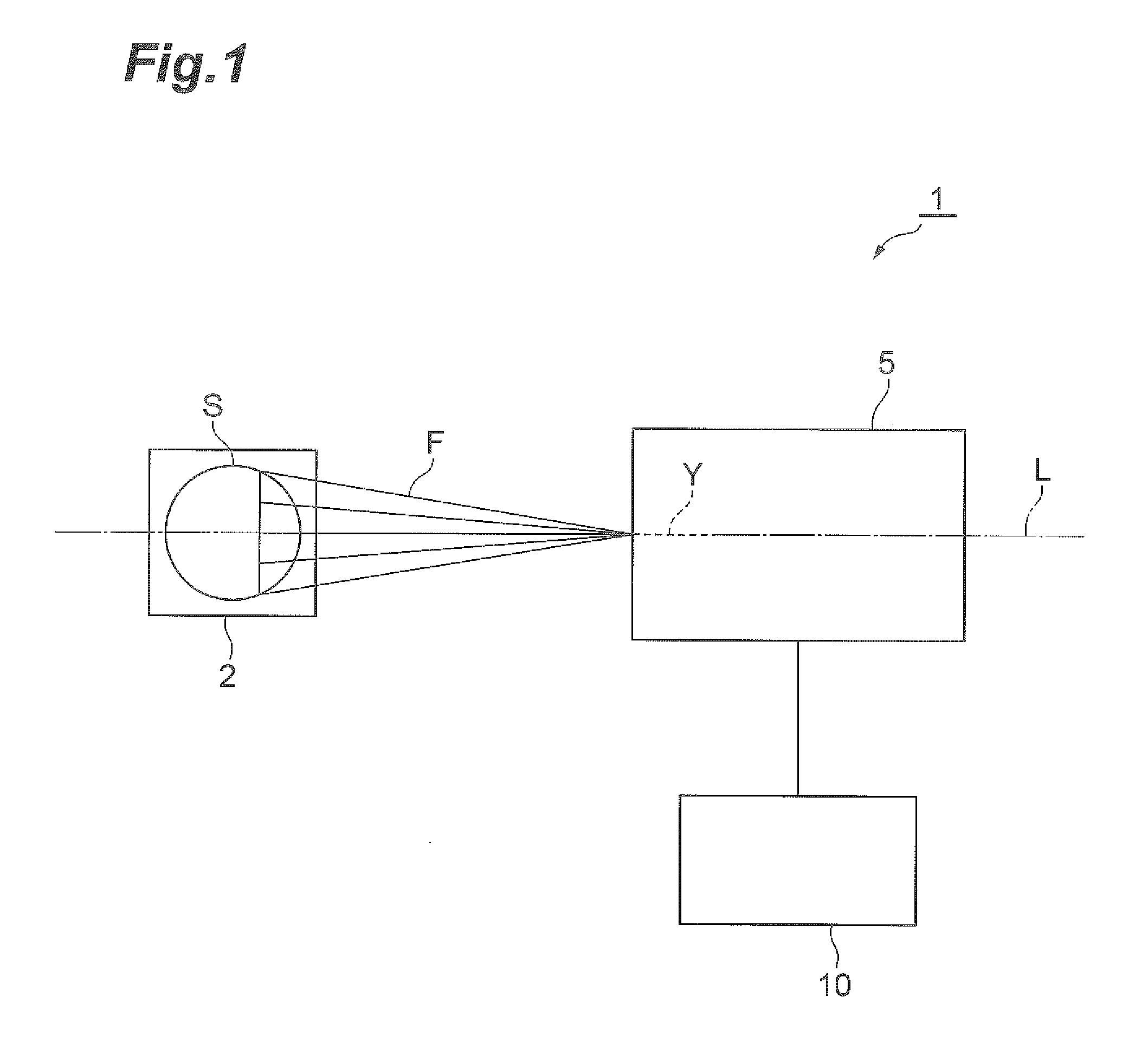
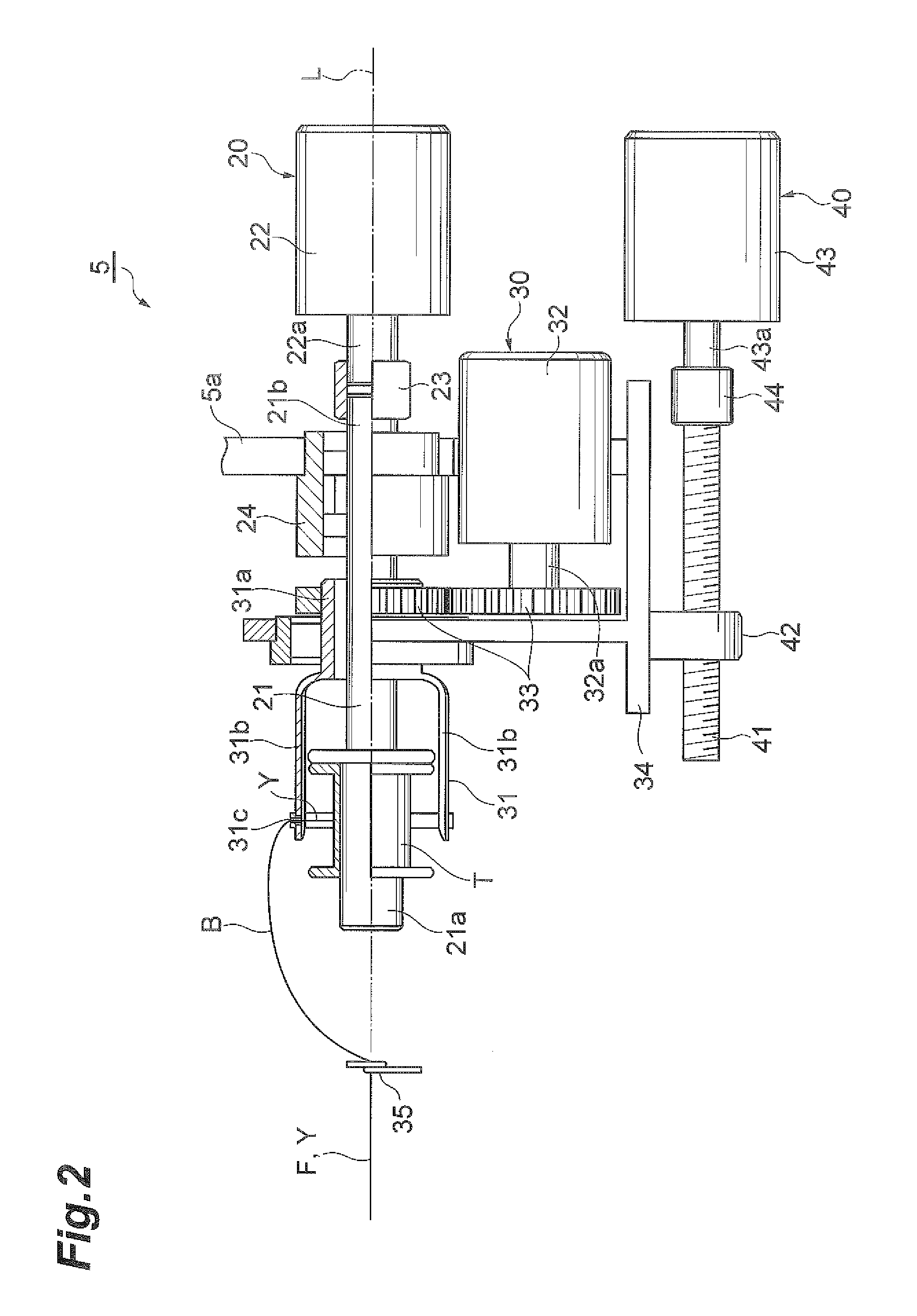
[0017]As shown in FIG . 1, a yarn producing apparatus 1 is an apparatus that produces carbon nanotube yarn (hereinafter referred to as “CNT yarn”) Y from carbon nanotube fibers (hereinafter referred to as “CNT fibers”) F while causing the CNT fibers F to run. The yarn producing apparatus 1 includes a substrate support 2, a twisting and winding device 5, and a controller 10. The substrate support 2 and the twisting and winding device 5 are arranged on a predetermined straight line L. The CNT fibers F run from the substrate support 2 toward the twisting and winding device 5. The controller 10 controls the operation of the twisting and winding device 5. The CNT fibers F preferably are a set of a p...


PUM

PropertyMeasurementUnit
driving forceaaaaaaaaaa
massaaaaaaaaaa
tensionaaaaaaaaaa

Abstract

A yarn producing apparatus produces CNT carbon nanotube) yarn from CNT fibers while causing the CNT fibers to run. The yarn producing apparatus includes a wind driving mechanism that causes a winding shaft provided with a winding tube to rotate about a winding centerline of the winding shaft to wind the CNT yarn onto the winding tube, a twist driving mechanism that causes a guide to rotate around the winding tube and guide the CNT yarn to the winding tube, to twist the CNT fibers and produce the CNT yarn while causing the CNT fibers, CNT yarn, or both to swirl, and a traverse driving mechanism that causes the guide to reciprocate relative to the winding tube along the winding centerline of the winding shaft to cause the CNT yarn to traverse the winding tube.

Description

BACKGROUND OF THE INVENTION[0001]1. Field of the Invention[0002]The present invention relates to a yarn producing apparatus for producing yarn from fibers while causing the fibers to run.[0003]2. Description of the Related Art[0004]An example of a yarn producing apparatus as described above is disclosed in Japanese Patent Application Laid-Open Publication No. 2010-65339. FIG. 1 of Japanese Patent Application Laid-Open Publication No. 2010-65339 illustrates a ring-type spinning apparatus that twists carbon nanotube fibers and produces carbon nanotube yarn while winding the carbon nanotube yarn.[0005]Carbon nanotube fibers are fibers having a relatively low load-bearing value and a relatively small mass. When the apparatus illustrated in FIG. 1 of Japanese Patent Application Laid-Open Publication No. 2010-65339 is applied to such carbon nanotube fibers, the traveler for yarn guide disposed on the ring fails to be rotated appropriately, and, as a result, the produced yarn may not have ...

Claims


Application Information

Patent Timeline
Patent Type & Authority Applications(United States)
IPC IPC(8): D01H1/115
CPCD01H1/115D01H1/04B65H54/2896B65H2701/314D01F9/127D02G3/16D10B2101/122
Inventor TAKASHIMA, HIROKI
Owner MURATA MASCH LTD
Why Eureka
Try Eureka