

Display apparatus and method of controlling display apparatus
- Summary
- Abstract
- Description
- Claims
- Application Information
AI Technical Summary
Benefits of technology
Problems solved by technology
Method used
Image

Examples
first embodiment
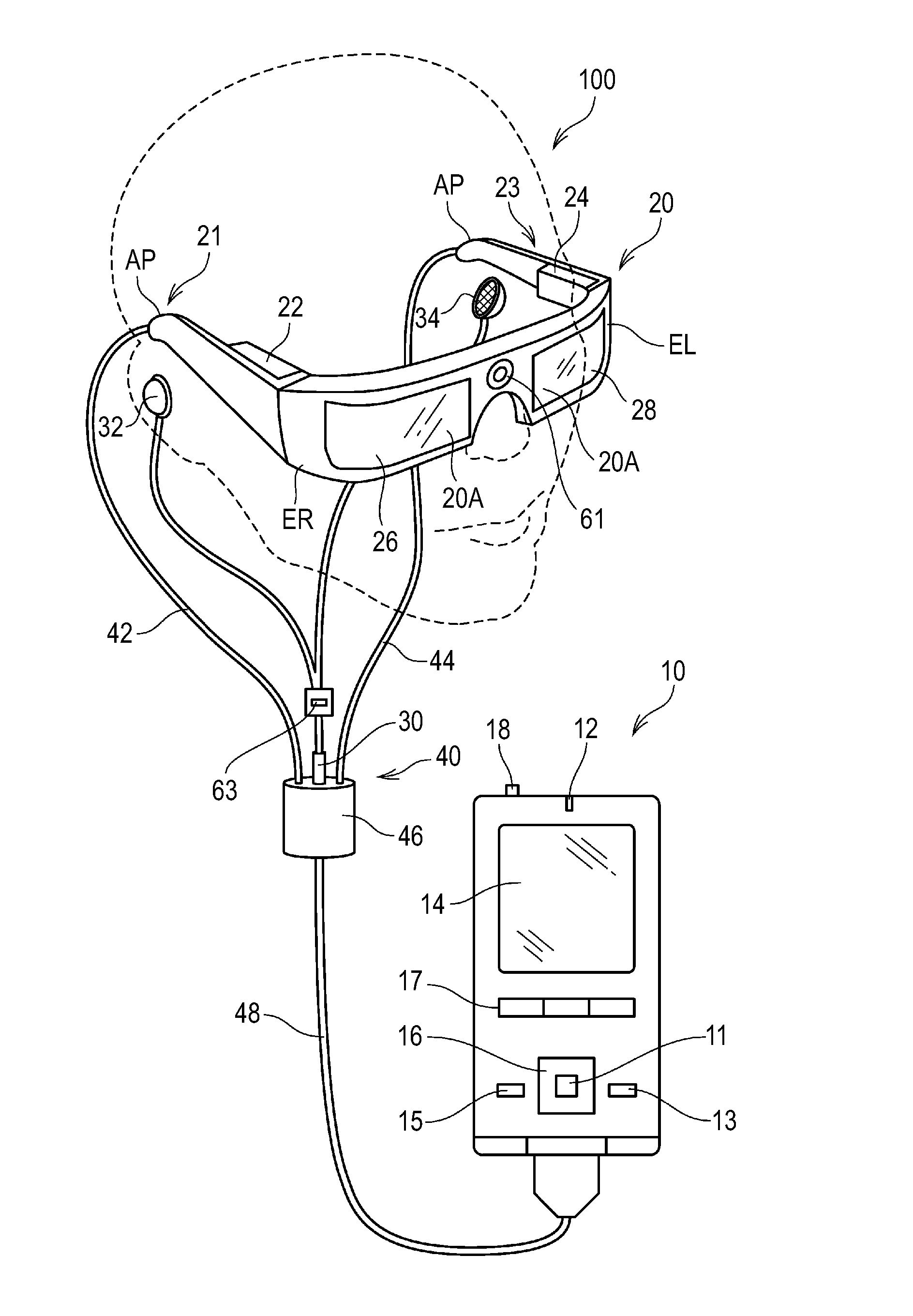
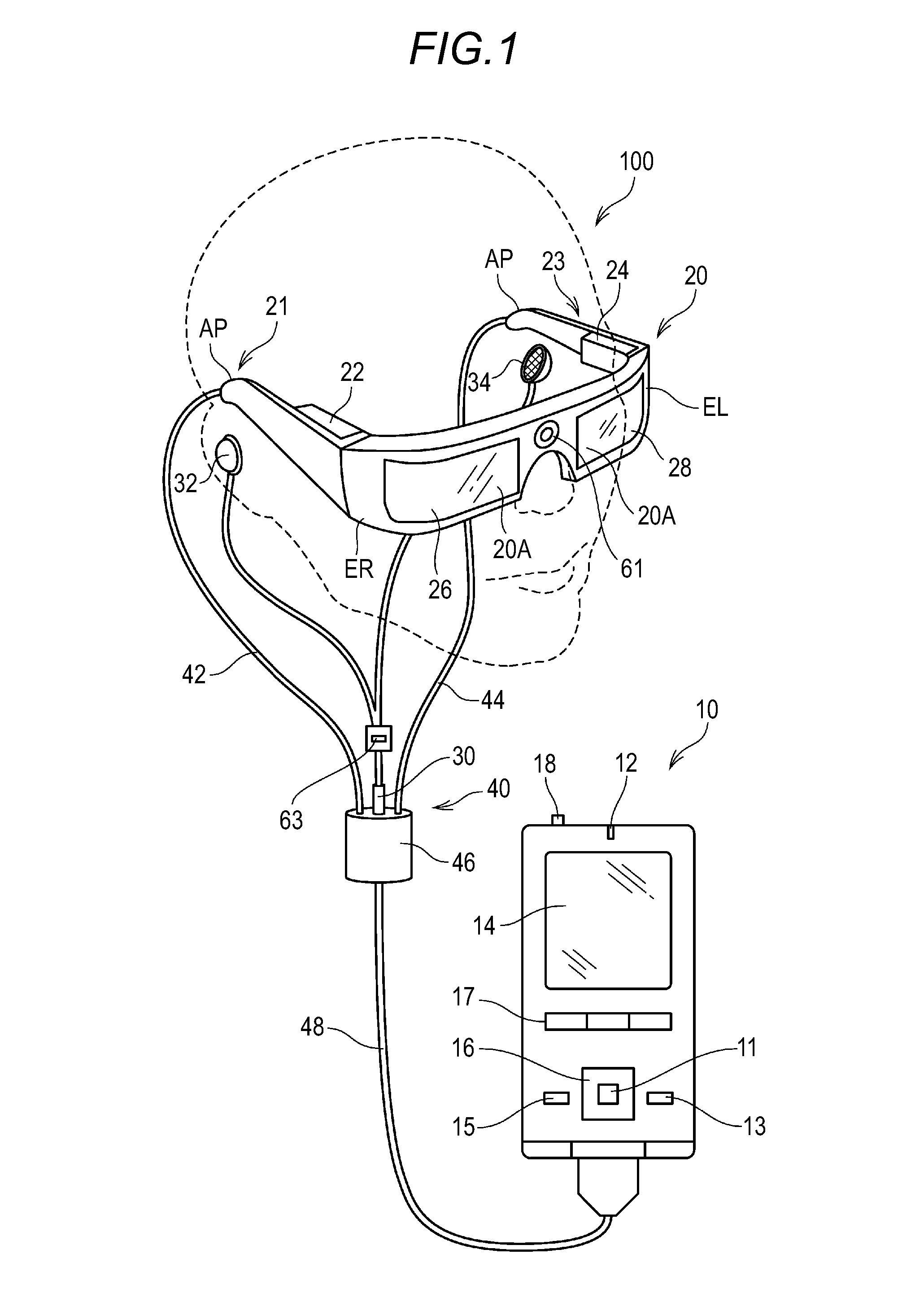
[0074]FIG. 1 is an explanatory diagram illustrating an appearance configuration of a head-mounted display apparatus 100 (display apparatus) according to a first embodiment to which the invention is applied.
[0075]The head-mounted display apparatus 100 includes an image display unit 20 (display unit) that causes a user to visually recognize a virtual image in a state in which the user wears the head-mounted display apparatus 100 on their head and a control device 10 that controls the image display unit 20. The control device 10 also functions as a controller by which the user operates the head-mounted display apparatus 100.
[0076]The image display unit 20 is a mounted body that is mounted on the head of the user and has a form of glasses in this embodiment. The image display unit 20 includes a right holding unit 21, a right display drive unit 22, a left holding unit 23, a left display drive unit 24, a right optical image display unit 26, a left optical image display unit 28, a camera 6...
second embodiment
[0175]FIGS. 7A and 7B are flowcharts illustrating operations of a head-mounted display apparatus 100 according to a second embodiment to which the invention is applied, where FIG. 7A illustrates operations of a control device 10, and FIG. 7B illustrates operations of an image display unit 20.
[0176]A configuration of the head-mounted display apparatus 100 according to the second embodiment is the same as that of the first embodiment. Since the control device 10 and the image display unit 20 have the configurations described above with reference to FIGS. 1 to 3, the same reference numerals will be given to configurations and functional blocks of the respective devices, and depictions and explanations thereof will be omitted.
[0177]FIGS. 7A and 7B are flowcharts that are executed when the head-mounted display apparatus 100 is started, for example, for performing setting in relation to a detection operation of a sub-control unit 150 by exchanging control data between the control unit 110...
third embodiment
[0232]FIG. 11 is a functional block diagram of the respective components in a head-mounted display apparatus 100B according to a third embodiment to which the invention is applied. In a configuration of the head-mounted display apparatus 100B illustrated in FIG. 11, the same reference numerals will be given to the same components as those in the head-mounted display apparatus 100 (FIG. 3) described above in the first embodiment, and the descriptions thereof will be omitted.
[0233]The head-mounted display apparatus 100B has a configuration that represents specific examples of the various sensors in the control device 10 and the various sensors in the image display unit 20 in the head-mounted display apparatus 100 according to the first embodiment.
[0234]That is, a control device 10B includes a position detection unit 420, an imaging unit 430, and a condition detection unit 440 as a configuration that was described above as the sensor IC 127 in the control device 10. The position detect...
PUM
 Abstract
Description
Claims
Application Information