Aerial fire-fighting bucket

a fire-fighting bucket and bucket body technology, applied in fire rescue, valve details, engine components, etc., can solve the problems of wasting wasting time, and wasting time, so as to facilitate the hose handling wear and tear, reduce the amount of time, and save the effect of saving fuel and other running costs which can be extremely expensiv

Inactive Publication Date: 2016-06-16
AERIAL FIRE CONTROL INT PTY LTD
View PDF3 Cites 6 Cited by
  • Summary
  • Abstract
  • Description
  • Claims
  • Application Information

AI Technical Summary

Benefits of technology

[0024]In accordance with an embodiment of the invention, two formers are provided. The first former is arranged to expand the widest diameter of the well wall. The second former is set above the first former so as to be located about three-quarters the way up the well wall. The inclusion of first and second formers assists with filling of the bucket by not allowing the well wall to collapse over the base plate during filling due to differential water pressure. Further, the inclusion of the second former ensures that the material of the well wall does not collapse to a position when the bucket begins to empty that would allow water to be retained around the bottom outer edge of the well wall.
[0025]The formers are preferably arranged for rapid expansion of the well wall. To this end, each former is preferably held in position on the well wall using, for example, at least one bracket. Only a relatively small amount of fluid (e.g. air) is required to expand each former to its full diameter and to a preferred pre-determined pressure setting. A compressor, preferably without a pressure tank, is used to expand the formers and will preferably be powered by an external 24V DC power socket on the aircraft. Such an a...

Problems solved by technology

Having the ability to fill the bucket in this way reduces the time between water drops, hopefully resulting in the fire being extinguished more quickly.
Filling the bucket locally also saves fuel and other running costs which can be extremely expensive.
Such rigging and lines may be easily fouled resulting in the inability to release water from the bucket and in an extreme situation this may result in the decision to jettison the bucket.
Buckets according to U.S. Pat. No. 65,829,809 also have a tendency to leak due to the inner dump valve not sealing correctly, the purse strings are very prone to wear and tend to have a poor drop pattern due to the inner dump valve flailing in the wind when the water is jettisoned.
This type of bucket is also very prone to sailing, causing the bucket to move from substantially below the helicop...

Method used


Image

  • Aerial fire-fighting bucket
  • Aerial fire-fighting bucket
  • Aerial fire-fighting bucket

Examples


Embodiment Construction

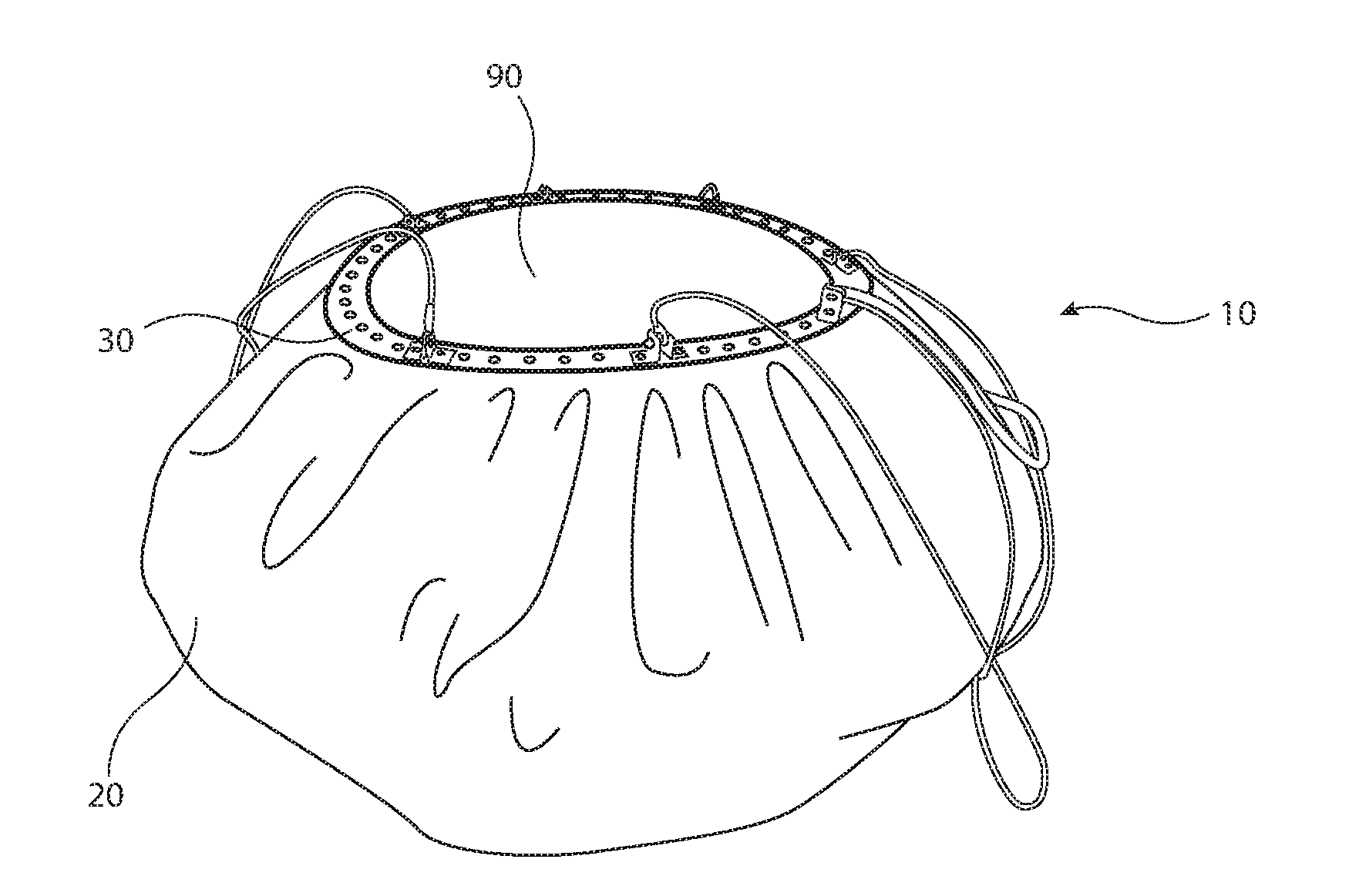
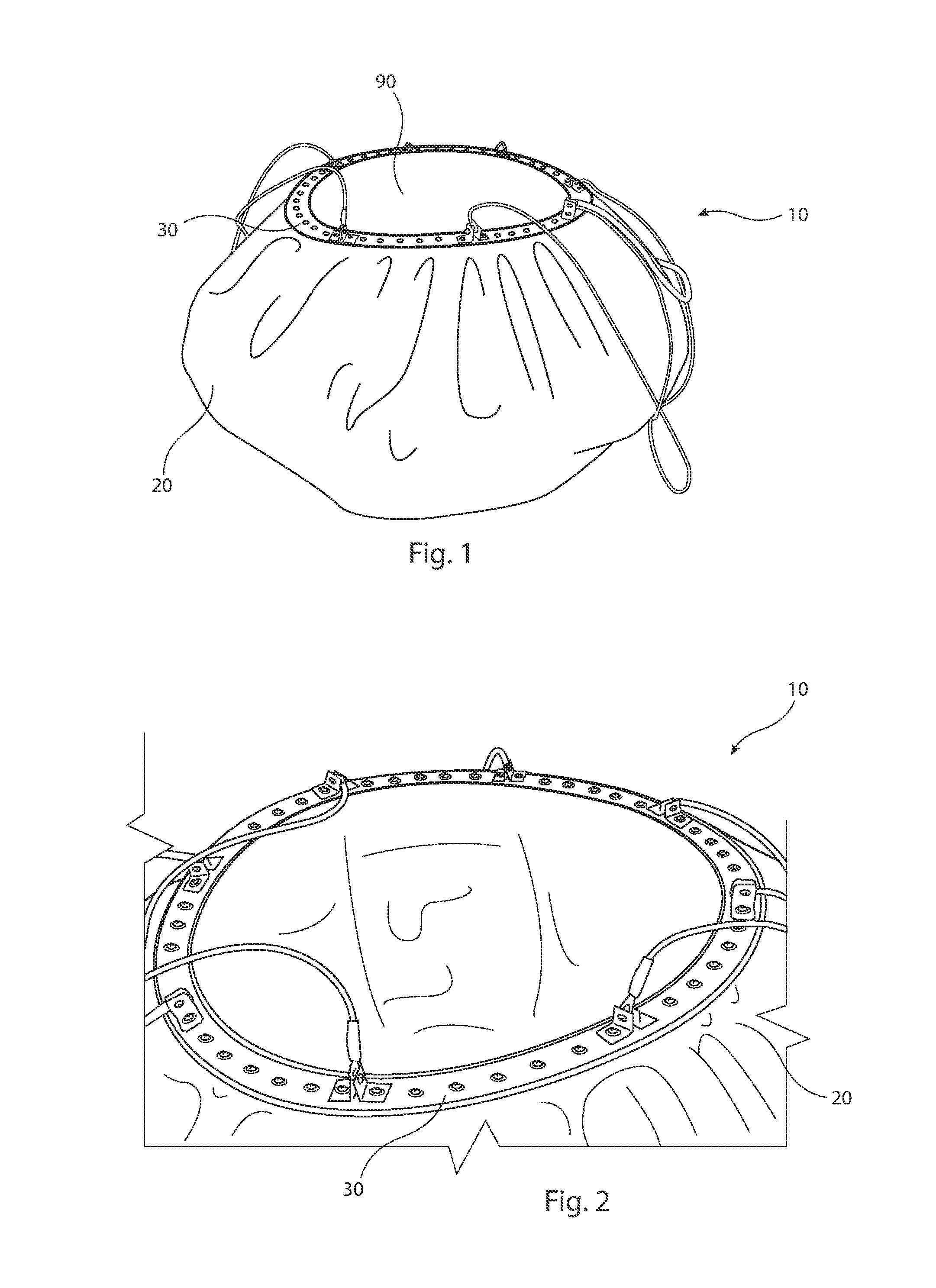
[0050]A fire-fighting bucket 10 in accordance with an embodiment of the invention will now be described. Bucket 10 as illustrated in FIGS. 1 to 10 is shown empty, that is, without any fire retardant (e.g. water) contained therein. It will be appreciated that the Figures also show the bucket 10 as it would appear generally resting on the ground and not as suspended from an aircraft (e.g. a helicopter) as would be the case during use thereof. Some of the Figures show the bucket 10 as it would appear at least partially suspended. During use of the bucket 10, rigging lines would be connected to the bucket 10 to enable the bucket 10 to be suspended from the helicopter. The shape of the bucket 10 as shown in FIGS. 1 to 10 is not reflective of the shape that would be achieved when the bucket 10 is filled with a fire retardant. The filled shape is more closely represented by FIG. 11.

[0051]To simplify the following discussion, the fire-fighting bucket 10 will hereafter be described in connec...


PUM


Abstract

The present invention relates to an aerial fire-fighting bucket. The bucket includes a base plate and a valve arrangement including at least one valve and a liner actuator. The base plate includes at least one aperture and the valve is arranged to block the aperture in a closed position and to allow fluid to pass from within the bucket through the aperture when in an open position. The valve is arranged to be moved by the linear actuator generally transversely across an upper face of the base plate between the closed position and the open position of the valve to progressively reveal the aperture.

Description

TECHNICAL FIELD[0001]The present invention relates to an aerial fire-fighting bucket of the type typically suspended below an aircraft. Typically, such an aircraft would be a helicopter.BACKGROUND OF INVENTION[0002]Large fires or fires in remote locations are often fought using aircraft to drop chemical fire retardants or water either directly on the fire or at nearby locations to create a fire break. Helicopters are often used for such operations because they do not require a dedicated landing strip and more importantly because they can fill their fire-fighting bucket without the need to land the helicopter. Typically, the bucket can be filled at a nearby body of water which may include a lake, dam, river or even a swimming pool. Having the ability to fill the bucket in this way reduces the time between water drops, hopefully resulting in the fire being extinguished more quickly. Filling the bucket locally also saves fuel and other running costs which can be extremely expensive.[00...

Claims


Application Information

Patent Timeline
IPC IPC(8): A62C3/02F16K31/04
CPCF16K31/04A62C3/0235
Inventor BLACK, CHRISTOPHER
Owner AERIAL FIRE CONTROL INT PTY LTD
Why Eureka
Try Eureka