Rotor blade extension

a technology of rotor blades and wind turbines, which is applied in the field of rotor blade extension and wind turbines, can solve the problems of reducing the annual energy production (aep) and an increase in the noise level of the turbine, the aerodynamic properties of the altered blade can significantly deviate from the original intended design, and the root extension is aerodynamically inefficient, so as to achieve constant, (or only negligible increase) the distance between the extended blade tip and the tower, the effect o

Inactive Publication Date: 2016-06-23
SIEMENS AG
View PDF9 Cites 23 Cited by
  • Summary
  • Abstract
  • Description
  • Claims
  • Application Information

AI Technical Summary

Benefits of technology

[0023]Therefore, in a particularly preferred embodiment of the invention, the rotor blade extension comprises a degree of “pre-bend” such that the airfoil extension portion is tilted outward from a longitudinal axis of the rotor blade. Here, the term “tilted outward” is to be understood such that the airfoil extension portion is bent to face “into the wind”, i.e. away from the tower. The pre-bent airfoil extension portion allows a favorable increase in rotor swept area, while maintaining an essentially constant, (or only negligibly increased) tip deflection. An advantage of the outwardly pre-bent airfoil extension portion of the rotor blade extension is that it becomes possible to upgrade existing wind turbine for which a tip deflection constraint applies.
[0024]In a preferred embodiment of the wind turbine according to embodiments of the invention, a rotor blade exhibits an “outwardly bent” shape when stationary, i.e. it bends away from the tower when stationary, and assumes a straighter shape when rotating. With a rotor blade extension according to embodiments of the invention, for which the airfoil extension portion has an outwardly pre-bent form, the rotor swept area of such a pre-bent blade can be increased even further, since the rotor blade extension is designed in such a way as to further increase the distance between the extended blade tip and the tower.
[0025]In a further preferred embodiment of the rotor blade extension, a longitudinal axis of the airfoil extension portion is skewed relative to the longitudinal axis of the rotor blade. When such a rotor blade extension is mounted onto a rotor blade, the blade exhibits “sweep”. The sweep introduced by the blade extension serves to further increase the bend-twist coupling, with the effect that blade loading is passively reduced. The positive effect is even more pronounced when the blade tip extension is mounted onto a “swept-back” blade, i.e. a blade for wh...

Problems solved by technology

When a blade fails to meet these design criteria, either through direct manufacturing deviations or through deterioration of the leading and/or trailing edges during the lifetime of the wind turbine, the result will be a decrease in annual energy production (AEP) and an increase in noise levels for the turbine.
Furthermore, a root extension is aerodynamically inefficient.
A further drawback of a root extension is that the airfoil part of the blade is effectively shifted “outward”, with the result that the aerodynamic properties of the altered blade can significantly deviate from the originally intended design, since the blade regions will operate in altered aerodynamic inflow conditions.
A drawback of known tip extensions is that the increas...

Method used


Image

  • Rotor blade extension
  • Rotor blade extension
  • Rotor blade extension

Examples


first embodiment

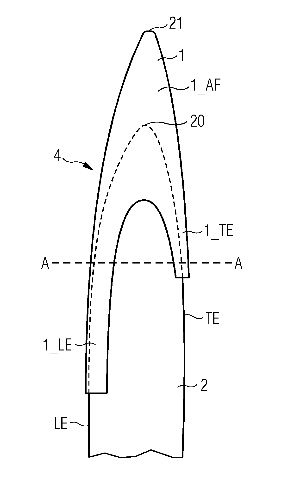
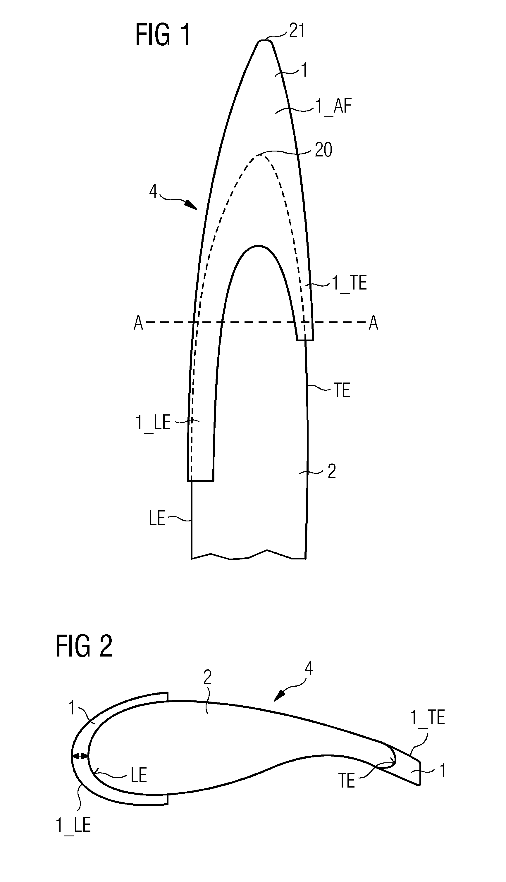
[0045]FIG. 1 shows the outboard part of an extended rotor blade 4 of a wind turbine 3. The extended rotor blade 4 comprises a rotor blade extension 1 according to embodiments of the invention, which is in place over the tip 20 of the rotor blade 2. The rotor blade 2 comprises a trailing edge TE and a leading edge LE. The rotor blade 2 is tapered, i.e. pointed, and comprises a tip 20. Reference sign 20 refers to the tip of the “original” rotor blade 2, i.e. the rotor blade 2 without any rotor blade extension. Once the rotor blade extension 1 is attached to the rotor blade 2, the extended rotor blade 4 is obtained. Reference sign 21 refers to the tip of the extended rotor blade 4, thus, it is also referred to as the “extended tip”21.

[0046]The rotor blade extension 1 is shown to comprise an airfoil extension portion 1_AF that effectively extends the length of the rotor blade 2; a leading edge portion 1_LE that is used to cover or extend a portion of the leading edge LE of the rotor bla...

second embodiment

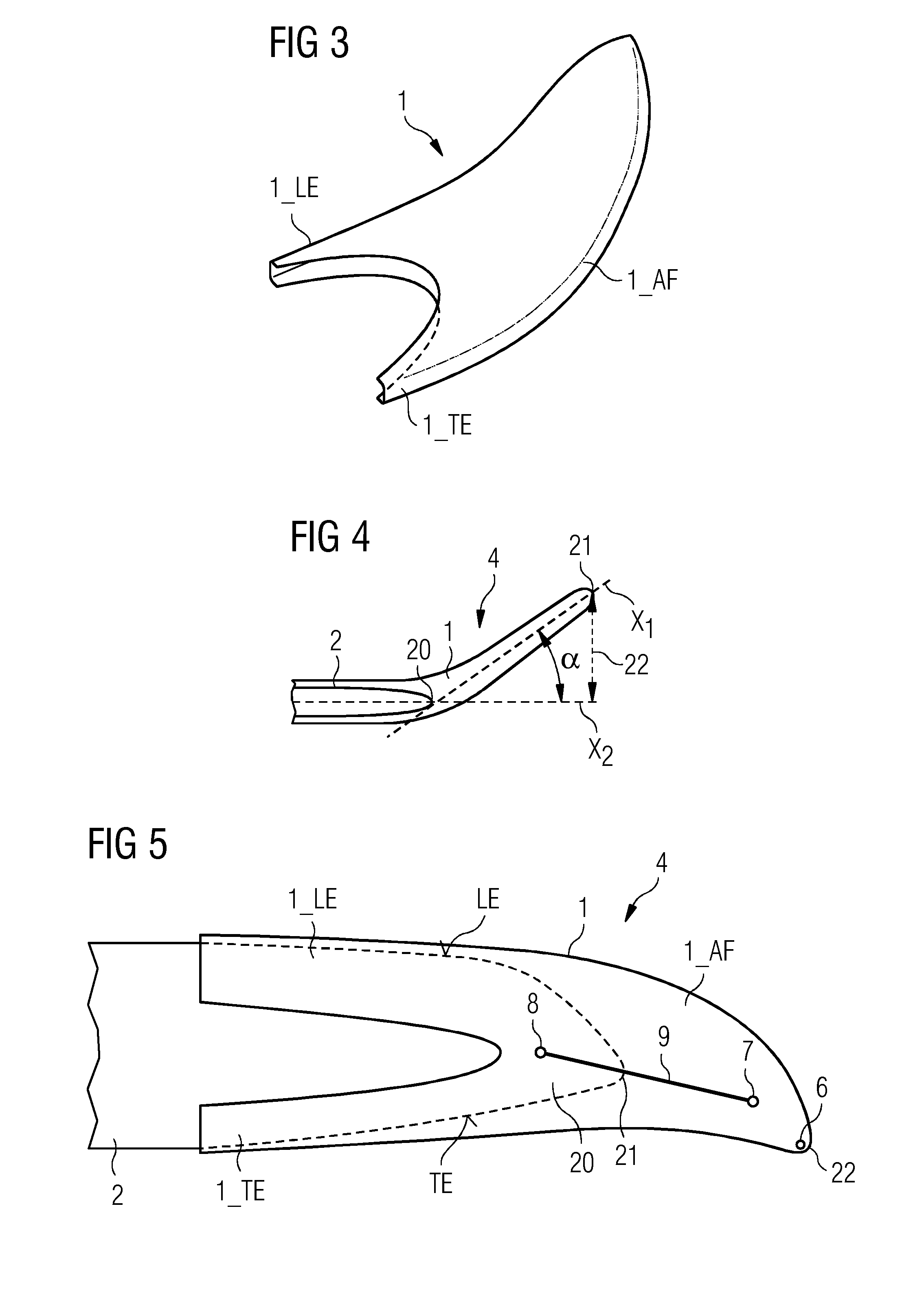
[0048]FIG. 3 shows a rotor blade extension 1 according to embodiments of the invention. Here, the rotor blade extension 1 exhibits a significant degree of pre-bend, i.e. the airfoil portion 1_AF is bent outwards so that, when mounted onto a rotor blade, the airfoil portion 1_AF will face “into the wind”.

[0049]The extent of the pre-bend is shown in cross-section in FIG. 4, which shows a longitudinal axis X2 of the rotor blade 2 and a longitudinal axis X1 extending through the airfoil portion 1_AF of the rotor blade extension 1.

[0050]A first approach to characterize and quantify the extent of the pre-bend of the rotor blade extension 1 is an angle α subtended by these axes X2, X1.

[0051]A second approach to characterize and quantify the extent of the pre-bend of the rotor blade extension 1 is the distance 22 between the extended tip 21 and the longitudinal axis X2. This distance 22 relates to the amount by which the distance between the tip of the rotor blade and the tower of the wind ...

third embodiment

[0054]FIG. 5 shows a rotor blade extension 1 according to embodiments of the invention. In this example, the portions 1_LE, 1_TE have essentially the same length. The rotor blade 2 comprises a swept-back tip, i.e. the tip of the blade is angled more towards the trailing edge TE than towards the leading edge LE. In this embodiment, the airfoil portion 1_AF is also “swept back”, so that the sweep of the original blade design is repeated or even increased by the sweep of the rotor blade extension 1. This embodiment can be combined with the embodiment of FIG. 4, for example, to give a rotor blade extension 1 that exhibits sweep as well as pre-bend.

[0055]The rotor blade extension 1 of FIG. 5 also comprises a drainage hole 6 for enabling liquid, such as water, to exit the inside of the extended rotor blade 4. Furthermore, the rotor blade extension 1 comprises an extension lightning receptor 7 for attracting lightning strikes, which typically strike a rotor blade in the proximity of the ti...


PUM


Abstract

A rotor blade extension for mounting over a tip of a wind turbine rotor blade, including an airfoil extension portion) configured to extend a length of the rotor blade, a leading edge portion configured to cover a profile of the leading edge of the rotor blade, and a trailing edge portion configured to cover a profile of the trailing edge of the rotor blade, is provided. A wind turbine including a number of rotor blades and a rotor blade extension mounted to each rotor blade is also provided.

Description

CROSS-REFERENCE TO RELATED APPLICATIONS[0001]This application claims priority to EP Application No. 14199679.3 having a filing date of Dec. 22, 2014, the entire contents of which are hereby incorporated by reference.FIELD OF TECHNOLOGY[0002]The following describes a rotor blade extension and a wind turbine.BACKGROUND[0003]Most of the wind energy that acts to turn the rotor of a wind turbine generator is harvested in the outermost part of wind turbine blades, and present-day wind turbines are designed to have increasingly large rotor diameters, whereby the rotor diameter is the diameter of a circle described by the rotor blade tips as they rotate.[0004]The outermost end of the blade, also referred to as the tip region, is subject to several strict design criteria, such as leading edge radius, profile contour, twist orientation, trailing edge thickness, etc. When a blade fails to meet these design criteria, either through direct manufacturing deviations or through deterioration of the...

Claims


Application Information

Patent Timeline
IPC IPC(8): F03D1/06
CPCF03D1/0633F03D1/0675F05B2230/80F05B2250/183F03D80/30F05B2240/307Y02E10/72Y02P70/50
Inventor GONZALEZ, ALEJANDRO GOMEZJENSEN, SUNE NIEMANN
Owner SIEMENS AG
Why Eureka
Try Eureka