
System, method, and apparatus for monitoring, regulating, or controlling fluid flow

Active Publication Date: 2016-06-23
DEKA PROD LLP
View PDF0 Cites 113 Cited by
  • Summary
  • Abstract
  • Description
  • Claims
  • Application Information

AI Technical Summary

Benefits of technology

The present invention relates to an apparatus for compressing a fluid tube. The apparatus includes an actuator that causes the two ends of a curved, elongated support member to approach each other, reducing the distance between them and compressing the tube. The invention also includes a valve with two curved, elongated support members that position the tube against each other to reduce its internal volume. Connecting members and a knob with a ratchet engage the curved, elongated support members to compress the tube. The actuator may be rotated to operate the valve. The technical effect of this invention is to provide a simple yet effective apparatus for compressing a fluid tube.

Problems solved by technology

Typically, such applications use an infusion pump, but such pumps may not be used in all situations or environments.

Method used


Image

  • System, method, and apparatus for monitoring, regulating, or controlling fluid flow
  • System, method, and apparatus for monitoring, regulating, or controlling fluid flow
  • System, method, and apparatus for monitoring, regulating, or controlling fluid flow

Examples


Embodiment Construction

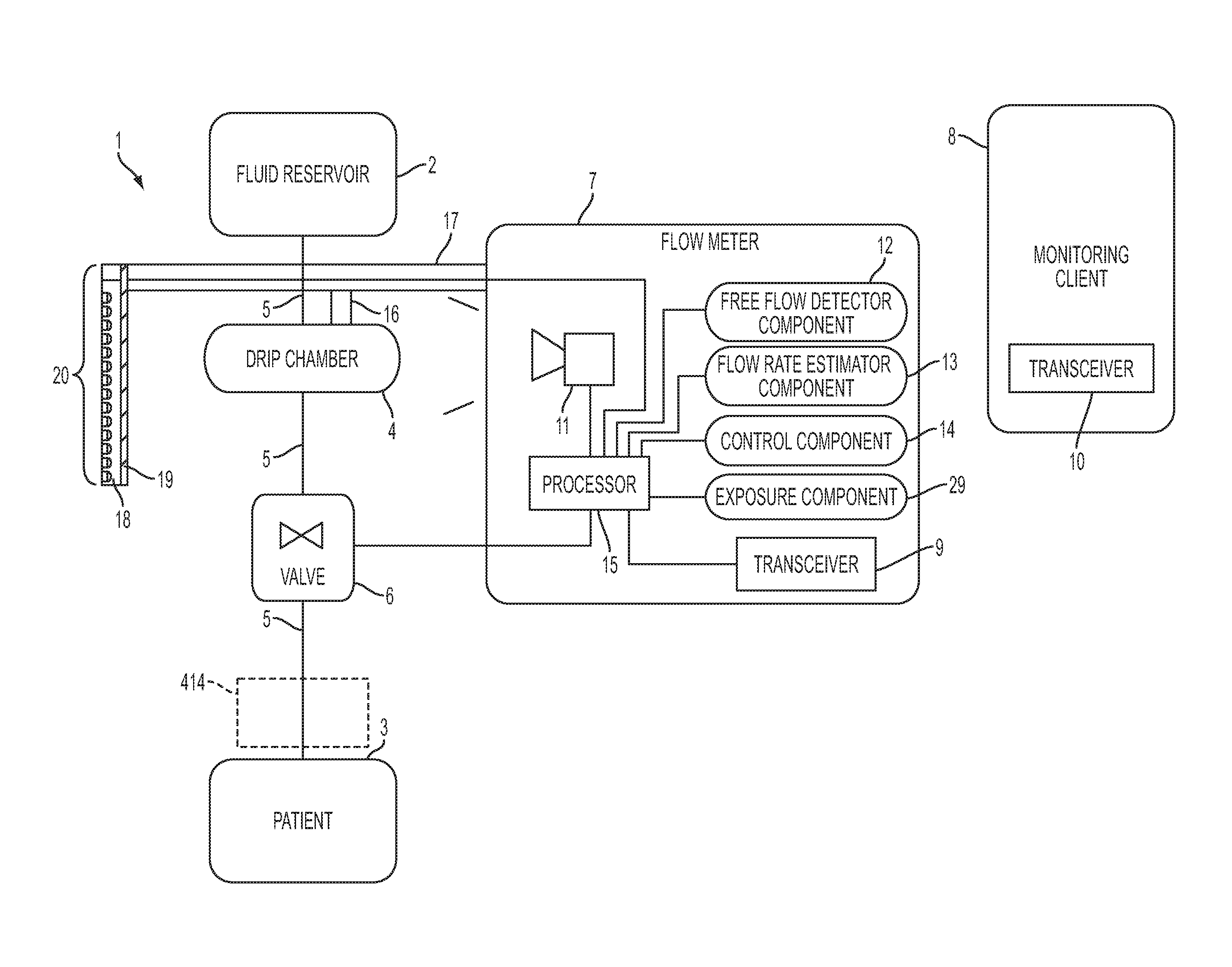
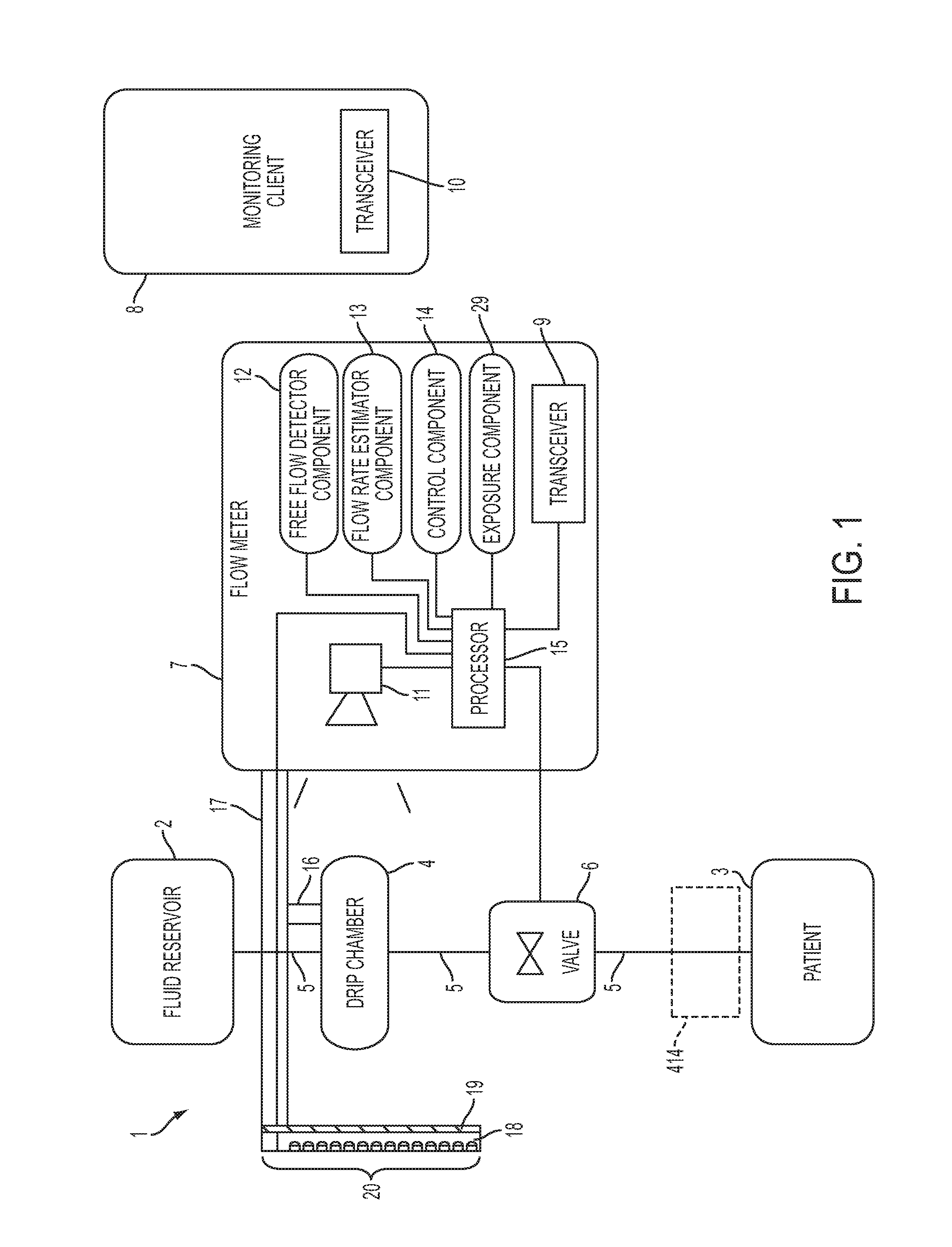
[0406]FIG. 1 shows a block diagram of a system 1 for regulating fluid flow in accordance with an embodiment of the present disclosure. For example, system 1 may regulate, monitor, and / or control the flow of fluid into a patient 3. The system 1 includes a fluid reservoir 2 for infusing fluid contained therein into the patient 3. The fluid reservoir 2 is gravity fed into a drip chamber 4 via a fluid tube 5. The fluid reservoir 2, the drip chamber 4, and the patient 3 may be considered as part of the system 1 or may be considered as separate or optional work pieces for the system 1 (e.g., any fluid reservoir 2 and drip chamber 4 may be used to treat any patient 3).

[0407]A flow meter 7 monitors the drip chamber 4 to estimate a flow rate of liquid flowing through the drip chamber 4. The fluid from the drip chamber 4 is gravity fed into a valve 6. The valve 6 regulates (i.e., varies) the flow of fluid from the fluid reservoir 2 to the patient 3 by regulating fluid flow from the drip chamb...


PUM


Abstract

A flow meter, and related system and method are provided. The flow meter includes a coupler, a support member, an image sensor, a valve, and one or more processors. The coupler is adapted to couple to a drip chamber. The support member is operatively coupled to the coupler. The image sensor has a field of view and is operatively coupled to the support member. The image sensor is positioned to view the drip chamber within the field of view. The one or more processors are operatively coupled to the image sensor to receive image data therefrom and to the actuator to actuate the valve. The one or more processors are configured to estimate a flow of fluid through the drip chamber and to actuate the valve to control the flow of fluid through the drip chamber to achieve a target flow rate.

Description

CROSS REFERENCE TO RELATED APPLICATIONS[0001]The present application is a continuation application of U.S. patent application Ser. No. 13 / 834,030, entitled System, Method, and Apparatus for Monitoring, Regulating, or Controlling Fluid Flow, (Attorney Docket No. K28) filed on Mar. 15, 2013, now U.S. Publication No. US 2013-0310990 A1, published on Nov. 21, 2013, which claims priority to and the benefit of the following:[0002]U.S. Provisional Patent Application Ser. No. 61 / 679,117, filed Aug. 3, 2012 and entitled System, Method, and Apparatus for Monitoring, Regulating, or Controlling Fluid Flow (Attorney Docket No. J30); and[0003]U.S. Provisional Patent Application Ser. No. 61 / 651,322, filed May 24, 2012 and entitled System, Method, and Apparatus for Electronic Patient Care (Attorney Docket No. J46), both of which are hereby incorporated herein by reference in their entireties.[0004]U.S. patent application Ser. No. 13 / 834,030, entitled System, Method, and Apparatus for Monitoring, Re...

Claims


Application Information

Patent Timeline
IPC IPC(8): G05B19/416G05D7/06
CPCG05B19/416G05B2219/41303G05D7/0617G05B2219/2607G06T7/13G06T7/174G05D7/0635G05B15/02G05D7/0676G06V10/751G06T7/0002
Inventor PERET, BOB DAVIDYOO, BRIAN H.KANE, DEREK G.KAMEN, DEANMURPHY, COLIN H.KERWIN, JOHN M.
Owner DEKA PROD LLP
Learn More