Capacitive sensing device and capacitive sensing method

a capacitive sensing and capacitive technology, applied in the field of capacitive sensing technologies, can solve the problems of misjudge the change of easy to be affected, and increase or decrease the capacitive value of the sensing point, so as to achieve the effect of improving the response speed of temperature change and maintaining the accuracy of the signal-reading process over tim

Active Publication Date: 2016-06-23
SALT INT CORP +1
View PDF2 Cites 11 Cited by
  • Summary
  • Abstract
  • Description
  • Claims
  • Application Information

AI Technical Summary

Benefits of technology

[0009]Therefore, the instant disclosure provides a capacitive sensing method and a device therefor to more correctly sense the touch manipulation.
[0012]According to the capacitive sensing device and the capacitive sensing method of the instant disclosure, the device detects the signals of the selected reference points in cycles. Based on the detection result, the default background noises (i.e., the reference measured values), and the relation settings for indicating the effect of temperature change to the position signals, the device can obtain the impact of temperature change on the position signals rapidly and adjust the position signals correspondingly. Therefore, the accuracy of a signal-reading process can be maintained over time and the response speed for temperature change can be improved.

Problems solved by technology

Specifically, the capacitive sensing devices (i.e., sensing devices belonging to capacitive sensing type) do not require materials having good properties in terms of stress and strain, and are not easily affected by environment light.
However, when the environment of the conventional capacitive sensing device transiently changes (e.g., temperature change in a short period of time), the capacitive value of the sensing point would increase or decrease according to the environment temperature, such that the conventional capacitive sensing device would misjudge the change of the capacitive value of the sensing point as a touch manipulation.

Method used


Image

  • Capacitive sensing device and capacitive sensing method
  • Capacitive sensing device and capacitive sensing method
  • Capacitive sensing device and capacitive sensing method

Examples


first embodiment

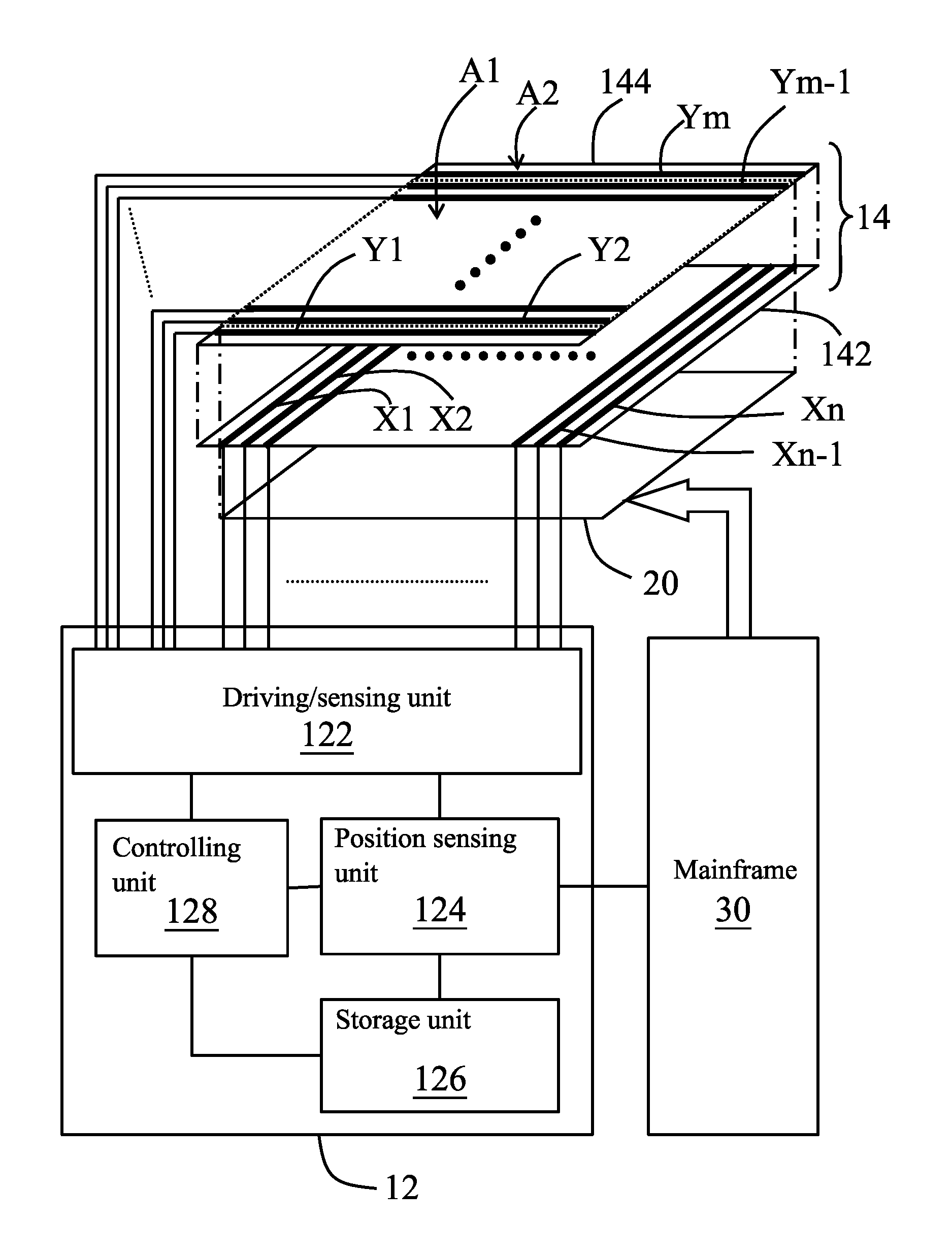
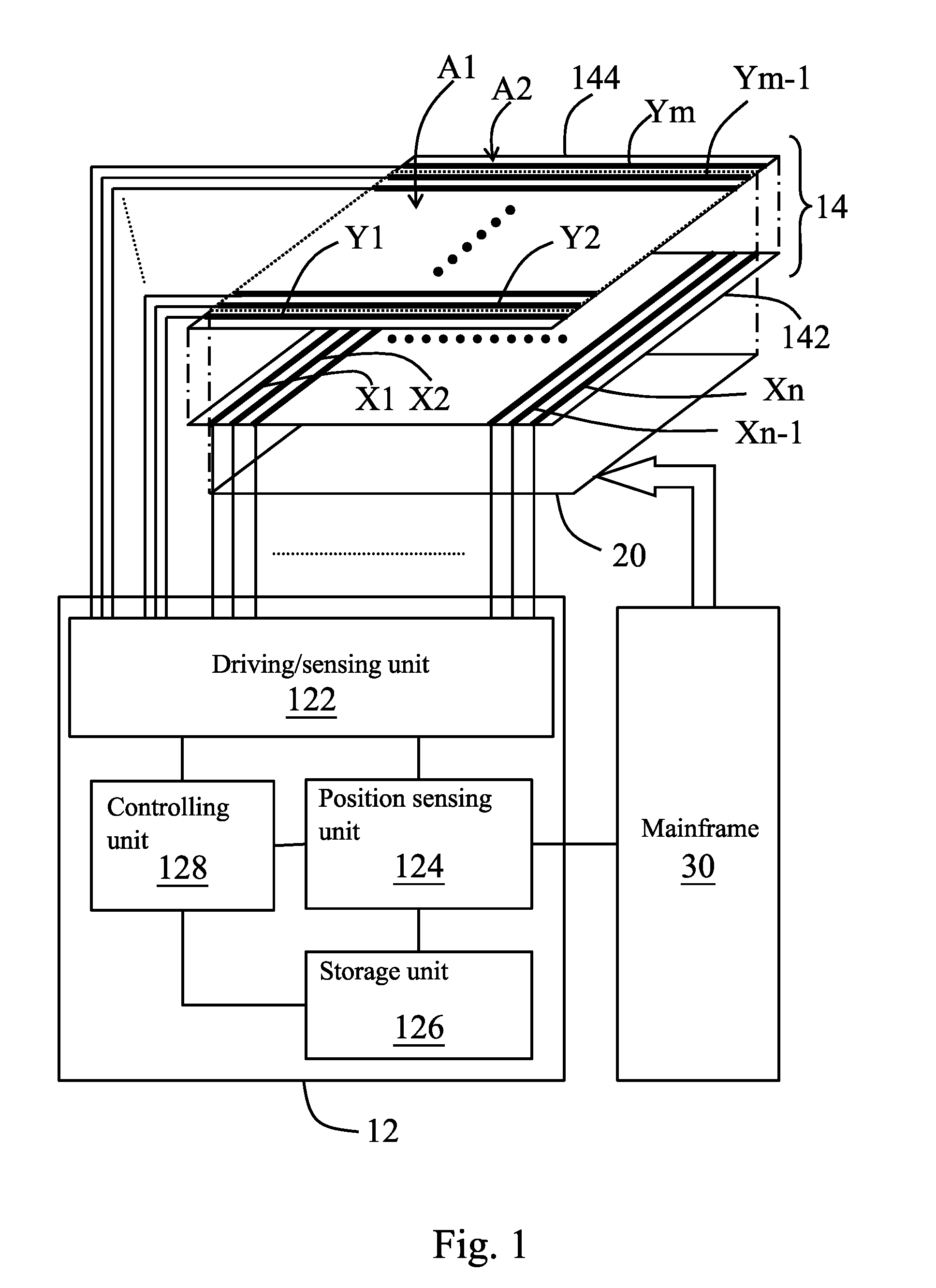
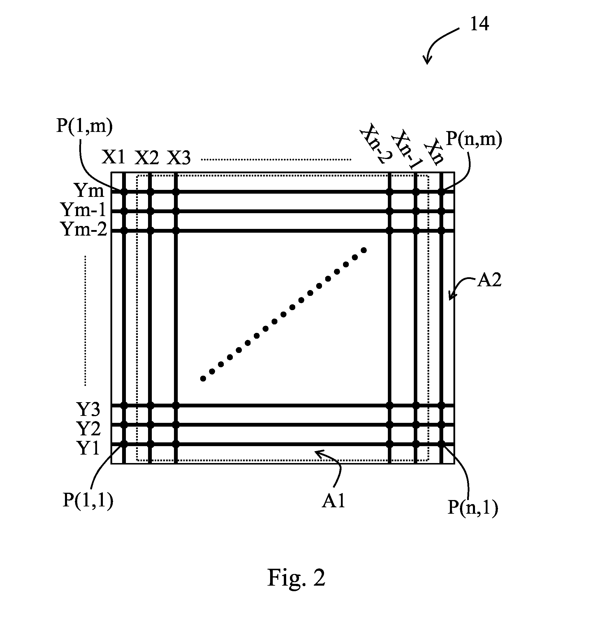
[0060]Details about the measuring step for measuring the first measured values in the step S11 and the step S53 and the measuring step for measuring the second measured values in the step S57 are further described. Referring to FIG. 1, FIG. 2, and FIG. 6, in the measuring step for measuring the first measured values in the step S11 and the step S53 and the measuring step for measuring the second measured values in the step S57, the reference points are a 2*1 number of sensing points located at each corner of the array (for example, P(1,1) and P(2,1), P(1,m) and P(2,m), P(n,1) and P(n-1,1), and P(n,m) and P(n-1,m)), and the driving / sensing unit 122 drives two first electrodes X1, X2 located at a first side of the array and two first electrodes Xn-1, Xn located at a second side of the array (step S71). Wherein, the first side is opposite to the second side.

[0061]Next, the driving / sensing unit 122 measures one second electrode Y1 located at a third side of the array and one second elec...

second embodiment

[0063]In the measuring step for measuring the first measured values in the step S11 and the step S53 and the measuring step for measuring the second measured values in the step S57, the reference points are one sensing point located at each corner of the array (for example, P(1,1), P(1,m), P(n,1), and P(n,m)), and the driving / sensing unit 122 drives one first electrode X1 located at the first side of the array (i.e., the leftmost first electrode) and one first electrode Xn located at the second side of the array (i.e., the rightmost first electrode) (step S71). Next, the driving / sensing unit 122 measures one second electrode Ym located at the third side of the array (i.e., the topmost second electrode) and one second electrode Y1 located at the fourth side of the array (i.e., the bottommost second electrode) to obtain the present measured values of the reference points (step S73).

third embodiment

[0064]In the measuring step for measuring the first measured values in the step S11 and the step S53 and the measuring step for measuring the second measured values in the step S57, the reference points are a 1*2 number of sensing points located at each corner of the array (for example, P(1,1) and P(1,2), P(1,m) and P(1,m-1), P(n,1) and P(n,2), and P(n,m-1) and P(n,m)), and the driving / sensing unit 122 drives one first electrode X1 located at the first side of the array and one first electrode Xn located at the second side of the array (step S71). Next, the driving / sensing unit 122 measures two second electrodes Ym, Ym-1 located at the third side of the array and two second electrodes Y1, Y2 located at the fourth side of the array to obtain the present measured values of the reference points (step S73).


PUM


Abstract

A capacitive sensing method includes detecting present measured values of plural reference points from plural sensing points; generating a present difference value according to the present measured values of the reference points and current reference measured values; comparing the present difference value with a threshold; detecting present measured values of the sensing points; generating plural position signals of the sensing points according to the present measured values of the sensing points and the current reference measured values; and controlling the output of the position signals according to a reference signal. When the present difference value is greater than the threshold, executing a procedure for refreshing background noise to refresh the current reference measured values. The sensing points are defined by intersected electrodes, configured to form an array, and correspond to the current reference measured values. The reference points are located at the periphery of the array.

Description

CROSS-REFERENCES TO RELATED APPLICATIONS[0001]This non-provisional application claims priority under 35 U.S.C. §119(a) on Patent Application No. 103144611 and 103144610, filed in Taiwan, R.O.C. on Dec. 19, 2014, the entire contents of which are hereby incorporated by reference.[0002]This application is related to U.S. Application Serial No. _____ (Docket: P144154US), entitled “CAPACITIVE SENSING DEVICE AND CAPACITIVE SENSING METHOD”, with an inventor LEE, SHANG-LI, that is being filed on the same day as the present application.BACKGROUND[0003]1. Technical Field[0004]The instant disclosure relates to capacitive sensing technologies, in particular, to a capacitive sensing device and method thereof capable of reducing the influence from transient environmental changes.[0005]2. Related Art[0006]For the sake of improving convenience of usage, more and more electronic devices adopt touch screens as operating interfaces. A user can touch graphics displayed on a touch screen of an electroni...

Claims


Application Information

Patent Timeline
Patent Type & Authority Applications(United States)
IPC IPC(8): G06F3/044G09G5/00G06F3/047
CPCG06F3/044G09G2300/0426G09G5/003G06F3/047G06F3/0418G06F3/0445G06F3/0446
Inventor LEE, SHANG-LI
Owner SALT INT CORP
Why Eureka
Try Eureka