Print data dividing apparatus, program, and recording medium

a technology of dividing apparatus and data, applied in the direction of instrumentation, total factory control, programme control, etc., can solve the problems of difficult positioning of easy deviation of joints, and difficulty in setting fitting portions of predetermined shapes to predetermined positions

Active Publication Date: 2016-06-30
CANON KK
View PDF3 Cites 4 Cited by
  • Summary
  • Abstract
  • Description
  • Claims
  • Application Information

AI Technical Summary

Benefits of technology

[0008]According to the aspect of the invention, the 3D image data is divided into the plurality of areas and, when the 3D shape data for division printing regarding the plurality of areas to be joined is generated, the joint portion of the kind corresponding to the thickness or the length of side of the joint surface of each area and the position among all of the areas is provided for the joint surface. Therefore, there is such an advantage that when a plurality of printed matters which were formed by a printing device and are related to a plurality of areas are mutually joined, their positioning can be easily performed and each printed matter is difficult to be deviated.

Problems solved by technology

However, in the case of dividing a model which does not have a predetermined shape, it is difficult to set fitting portions of predetermined shapes to predetermined positions.
If a model is designed in such a manner that no fitting portions are provided for the model to be divided and the model is rectilinearly divided, there is also such a problem that when the divided models are joined, their positioning is difficult and, further, their joints are easily deviated.

Method used


Image

  • Print data dividing apparatus, program, and recording medium
  • Print data dividing apparatus, program, and recording medium
  • Print data dividing apparatus, program, and recording medium

Examples


first embodiment

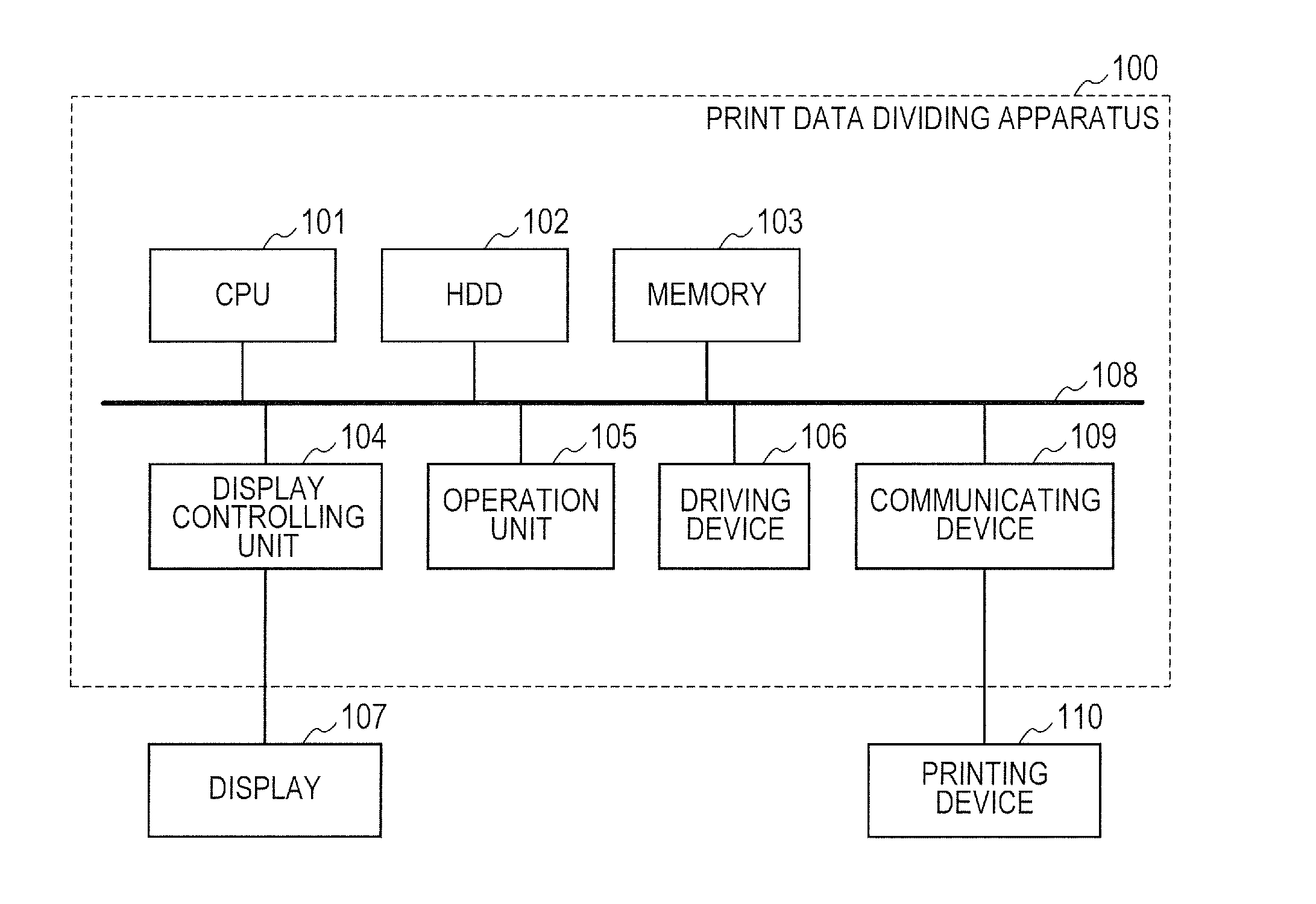
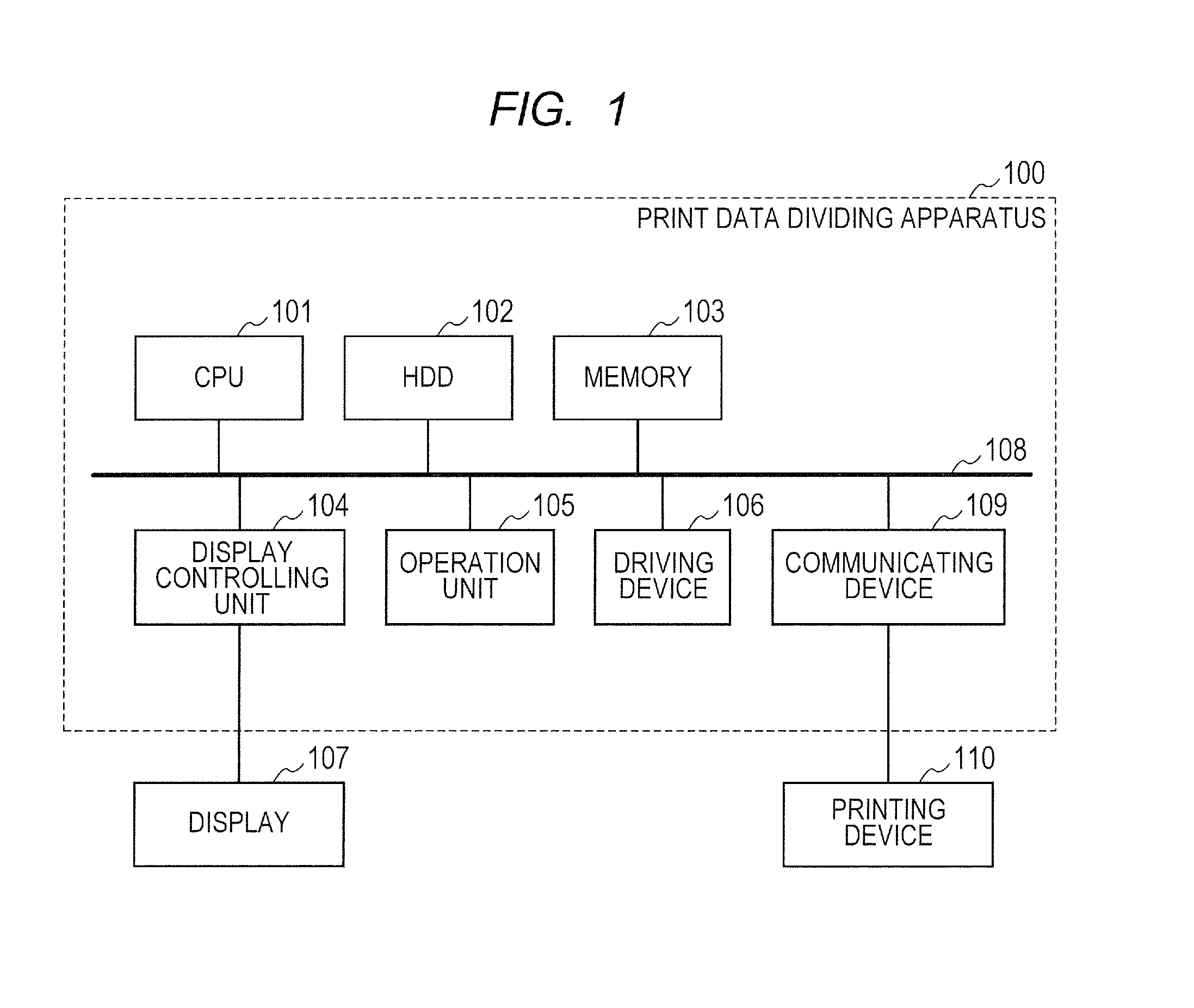
[0019]FIG. 1 illustrates a construction of a print data dividing apparatus 100 according to the first embodiment of the invention. As illustrated in FIG. 1, the print data dividing apparatus 100 can be constructed by using a general computer.

[0020]The print data dividing apparatus 100 has a central processing unit (CPU) 101, a hard disk drive (HDD) 102, a memory 103, a display controlling unit 104, an operation unit 105, a driving device 106, and a communicating device 109 which are connected to an internal bus 108. The units and devices 101 to 106 and 109 connected to the internal bus 108 mutually communicate data through the internal bus 108.

[0021]3D image data, 2D image data, other data, various kinds of programs by which the CPU 101 operates, and the like are stored in the HDD 102. The memory 103 is constructed by, for example, a RAM. In accordance with the programs stored in the HDD 102, the CPU 101 controls each unit and each device of the print data dividing apparatus 100 by ...

second embodiment

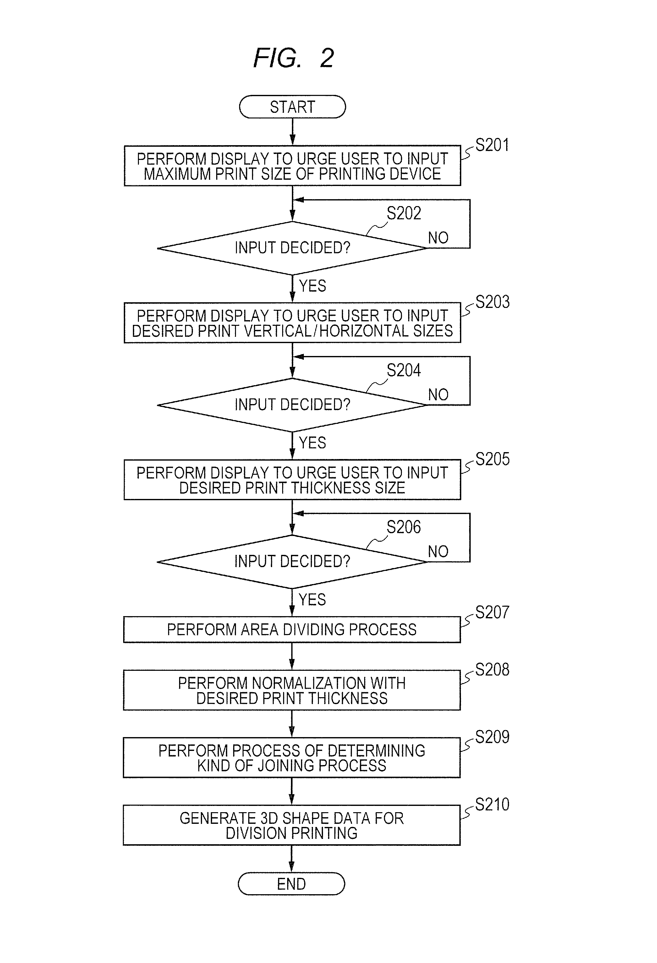
[0140]The second embodiment of the invention relates to a dividing method of 3D image data in which distance information has been added to 2D image information every pixel. In the embodiment, the 3D image data is divided into a plurality of areas on the basis of the specification (maximum print size) of the printing device and is converted into 3D shape data for division printing provided with the convex or concave tongue-and-groove joint portion on the basis of lengths of sides of the joint surface of each area and the position of the target area among all of the plurality of areas.

[0141]FIG. 6 is a flowchart for generating 3D shape data for division printing regarding the area provided with a tongue-and-groove joint portion. FIG. 7 is a flowchart for determining the kind of tongue-and-groove joining process. FIGS. 8A to 8D are conceptual diagrams illustrating divided areas and shapes of tongue-and-groove joint portions provided in the areas. FIGS. 6 to 8D will now be described tog...


PUM

PropertyMeasurementUnit
areaaaaaaaaaaa
areasaaaaaaaaaa
areaaaaaaaaaaa

Abstract

A print data dividing apparatus has: a dividing unit for dividing 3D image data having image / distance information every pixel into a plurality of areas; a determining unit for determining a kind of joining process to a joint surface of a target area among the plural areas based on a position of the target area and a thickness of the joint surface or a length of side of the joint surface; and a generating unit for generating 3D shape data for division printing about the target area in which a joint portion corresponding to the determined joining process kind has been provided for the joint surface. There is such an advantage that printed matters regarding the areas formed by a printing device can be easily positioned when mutually joining them and that each printed matter is difficult to be deviated.

Description

BACKGROUND OF THE INVENTION[0001]1. Field of the Invention[0002]The present invention relates to a print data dividing apparatus and a program for dividing print data into a plurality of areas and printing them and to a recording medium in which such a program has been recorded.[0003]2. Description of the Related Art[0004]A manufacturing method of a model whereby a first portion and a second portion of the model are molded based on three-dimensional (hereinbelow, referred to as 3D) shape data and the molded first and second portions are unitedly by mutually joining them has been known. Japanese Patent Application Laid-Open No. H11-216273 discloses a manufacturing method of a model whereby a head portion and a body portion of the model are prepared by materials of different qualities, the head portion and the body portion are molded based on 3D shape data, and the molded head portion and body portion are integrated by mutually joining them.[0005]In Japanese Patent Application Laid-Op...

Claims


Application Information

Patent Timeline
Patent Type & Authority Applications(United States)
IPC IPC(8): B29C67/00G05B19/4099
CPCB29C67/0088G05B19/4099B33Y50/02G05B2219/49007G05B2219/35134B33Y50/00Y02P90/02
Inventor TANAKA, SHUYA
Owner CANON KK
Why Eureka
Try Eureka