
Lock

a technology of locks and locks, applied in the field of locks, can solve the problems of time-consuming and laborious, system widespreadness, removal and replacement of such locks, etc., and achieve the effect of facilitating the sliding movement of the master tumbler

Active Publication Date: 2016-06-30
TRITEQ LOCK & SECURITY L L C
View PDF1 Cites 16 Cited by
  • Summary
  • Abstract
  • Description
  • Claims
  • Application Information

AI Technical Summary

Benefits of technology

The patent describes a lock driver for a lock that can be easily installed and used with existing lock structures. The lock driver includes a lock cylinder body, an actuation attachment portion, and an adapter structure. The lock cylinder body is positioned and rotatable within a bushing and includes a slot for a master tumbler. The actuation attachment portion extends from the front end of the lock cylinder body and includes an attachment interface for user manipulation. The adapter structure is associated with the back end of the lock cylinder body and interfaces with an existing lock structure. The lock driver is substantially precluded from axial movement and can be rotated within the bushing. The technical effects of this invention include improved ease of installation, compatibility with existing lock structures, and enhanced security.

Problems solved by technology

Such systems are ubiquitous, however, there are nevertheless drawbacks.
Additionally, the removal and replacement of such locks (necessitated by the changing of the duty of a piece of furniture, dismissal of an employee, loss of a set of keys, etcetera) is very time consuming and labor intensive.

Method used


Image

  • Lock
  • Lock
  • Lock

Examples


Embodiment Construction

[0083]While this invention is susceptible of embodiment in many different forms, there is shown in the drawings and described herein in detail a specific embodiment with the understanding that the present disclosure is to be considered as an exemplification and is not intended to be limited to the embodiment illustrated.

[0084]It will be understood that like or analogous elements and / or components, referred to herein, may be identified throughout the drawings by like reference characters. In addition, it will be understood that the drawings are merely schematic representations of the invention, and some of the components may have been distorted from actual scale for purposes of pictorial clarity.

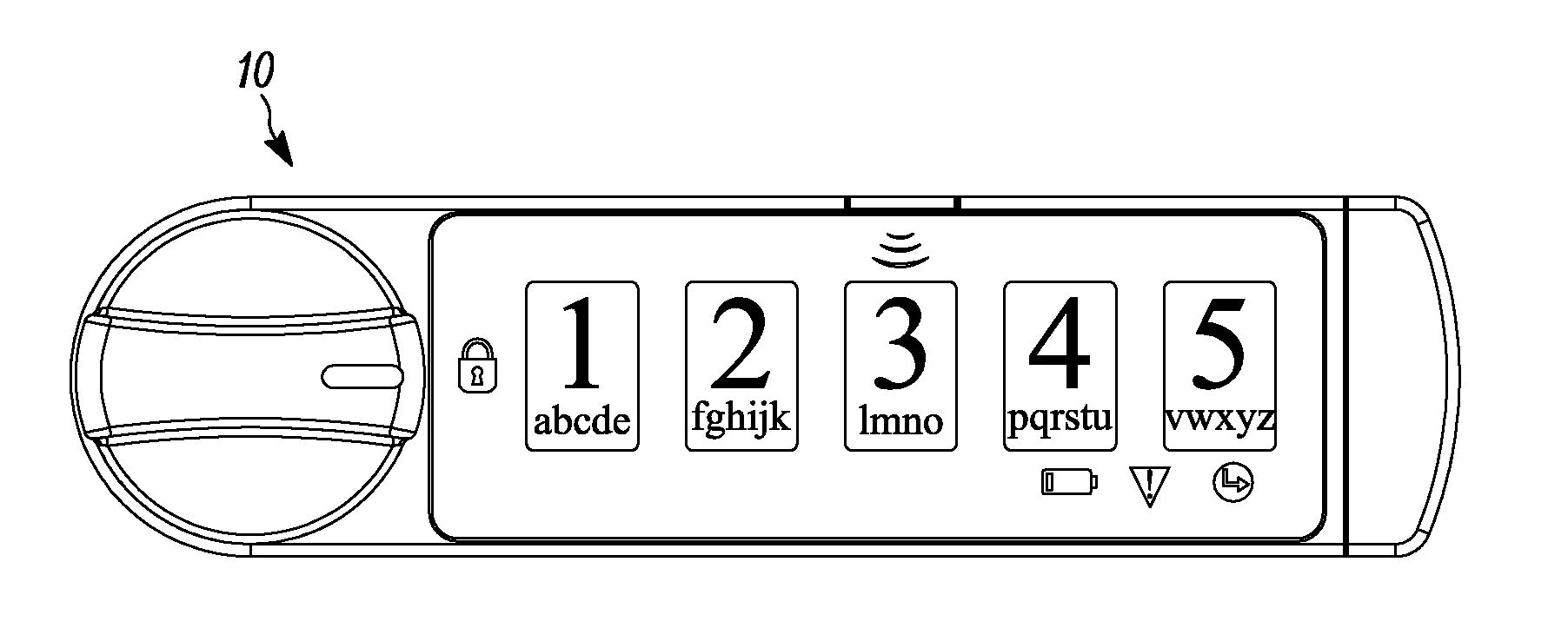
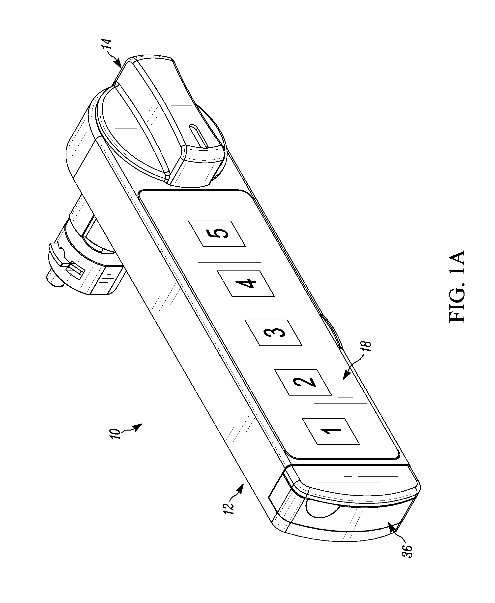
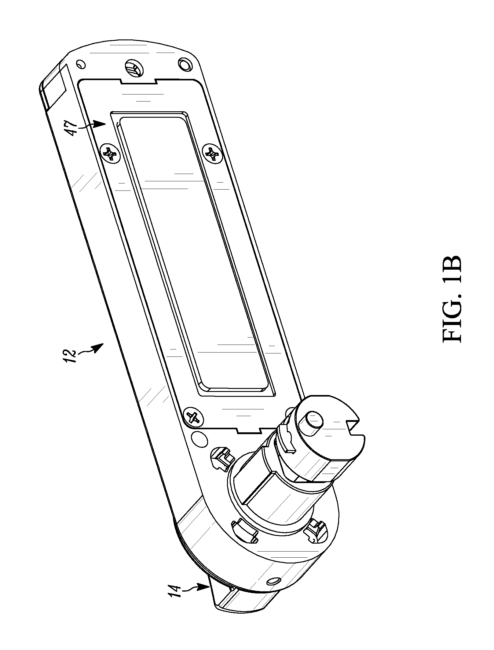
[0085]Referring now to the drawings and in particular to FIGS. 1 and 1A, the lock of the present invention is shown generally at 10. The lock 10 may be utilized in a number of different environments and in association with a number of different installations, including but not limited to, doo...


PUM


Abstract

A lock driver for a lock, including a lock cylinder body, an actuation attachment portion and an adapter structure. The lock cylinder body has a front end, a back end opposite the front end and an outer surface. The lock cylinder is positionable and rotatable within a bushing. The actuation attachment portion extends from the front end of the lock cylinder body. The actuation attachment portion includes an attachment interface that is structurally configured for coupling to a user maniuplatable structure. The adapter structure is associated with the back end of the lock cylinder body. The adapter structure is structurally configured to interface with an existing lock structure.

Description

CROSS-REFERENCE TO RELATED APPLICATION[0001]The present application is a continuation-in-part of U.S. patent application Ser. No. 14 / 719,218 filed May 21, 2015, entitled “Lock”, the entire specification of which is hereby incorporated by reference, which is a continuation of PCT Patent Application No. PCT / US2014 / 038016 filed May 14, 2014, entitled “Lock” the entire specification of which is hereby incorporated by reference, which claims priority from U.S. Provisional Patent Application Ser. No. 61 / 823,685, filed May 15, 2013, entitled “Hybrid-Electronic Core Lock”, the entire specification of which is hereby incorporated by reference.BACKGROUND OF THE DISCLOSURE[0002]1. Field of the Disclosure[0003]The disclosure relates in general to locks, and more particularly, to a core lock that is configured to provide electronic locking and unlocking of a lock. While not limited thereto, such a lock is well suited for use in association with furniture and cabinets, including as a retrofit to ...

Claims


Application Information

Patent Timeline
Patent Type & Authority Applications(United States)
IPC IPC(8): E05B47/00E05B41/00E05B37/00E05B15/00E05B17/00
CPCE05B47/00E05B15/00E05B17/00E05B2047/0097E05B41/00E05B2047/0048E05B37/00E05B47/0012E05B47/0657E05B47/0673E05B63/0056E05C3/042E05B15/0053E05B2047/0024E05B2047/0054E05B2047/0058Y10T70/7062G07C9/00174G07C9/0069G07C9/30E05B37/0041E05B1/003E05B15/0013E05C3/12
Inventor ROATIS, CALINDENISON, WILLIAM
Owner TRITEQ LOCK & SECURITY L L C
Learn More