
OLED Display Device

a light-emitting diode and display device technology, applied in the field of organic light-emitting diodes (oled) display devices, can solve the problems of not fully compensating for unique characteristics and not reflecting changes in the unique characteristics of transistors, so as to reduce or remove luminance differences and improve image quality

Active Publication Date: 2016-06-30
LG DISPLAY CO LTD
View PDF5 Cites 20 Cited by
  • Summary
  • Abstract
  • Description
  • Claims
  • Application Information

AI Technical Summary

Benefits of technology

The present invention provides an OLED display device that can repeatedly sense and compensate for changes in the threshold voltage of its subpixels. By doing so, the device can correct differences in threshold voltage between the driving transistors, resulting in improved image quality and the removal of stains on screens with low-grayscale luminance. Additionally, the device can sens and compensate for the threshold voltage in more precise units, allowing for better compensation of the threshold voltage.

Problems solved by technology

However, this approach of compensating the unique characteristics of a transistor, such as a threshold voltage, does not reflect changes in the unique characteristics of the transistor, such as the threshold voltage.
In addition, this approach fails to completely compensate for the unique characteristics, such as the threshold voltage, since a sensor and a compensation circuit of an OLED display device have different resolutions.

Method used


Image

  • OLED Display Device
  • OLED Display Device
  • OLED Display Device

Examples


Embodiment Construction

[0052]Reference will now be made in detail to embodiments of the present invention, examples of which are illustrated in the accompanying drawings. Throughout this document, reference should be made to the drawings, in which the same reference numerals and signs will be used to designate the same or like components.

[0053]It will also be understood that, although terms such as “first,”“second,”“A,”“B,”“(a)” and “(b)” may be used herein to describe various elements, such terms are used to distinguish one element from another element. The substance, sequence, order or number of these elements is not limited by these terms. It will be understood that when an element is referred to as being “connected to” or “coupled to” another element, not only can it be “directly connected” or “coupled to” the other element, but also can it be “indirectly connected or coupled to” the other element via an “intervening” element. In the same context, it will be understood that when an element is referred...


PUM


Abstract

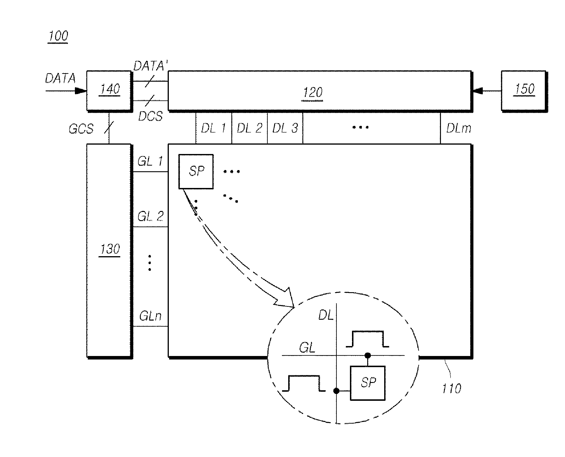
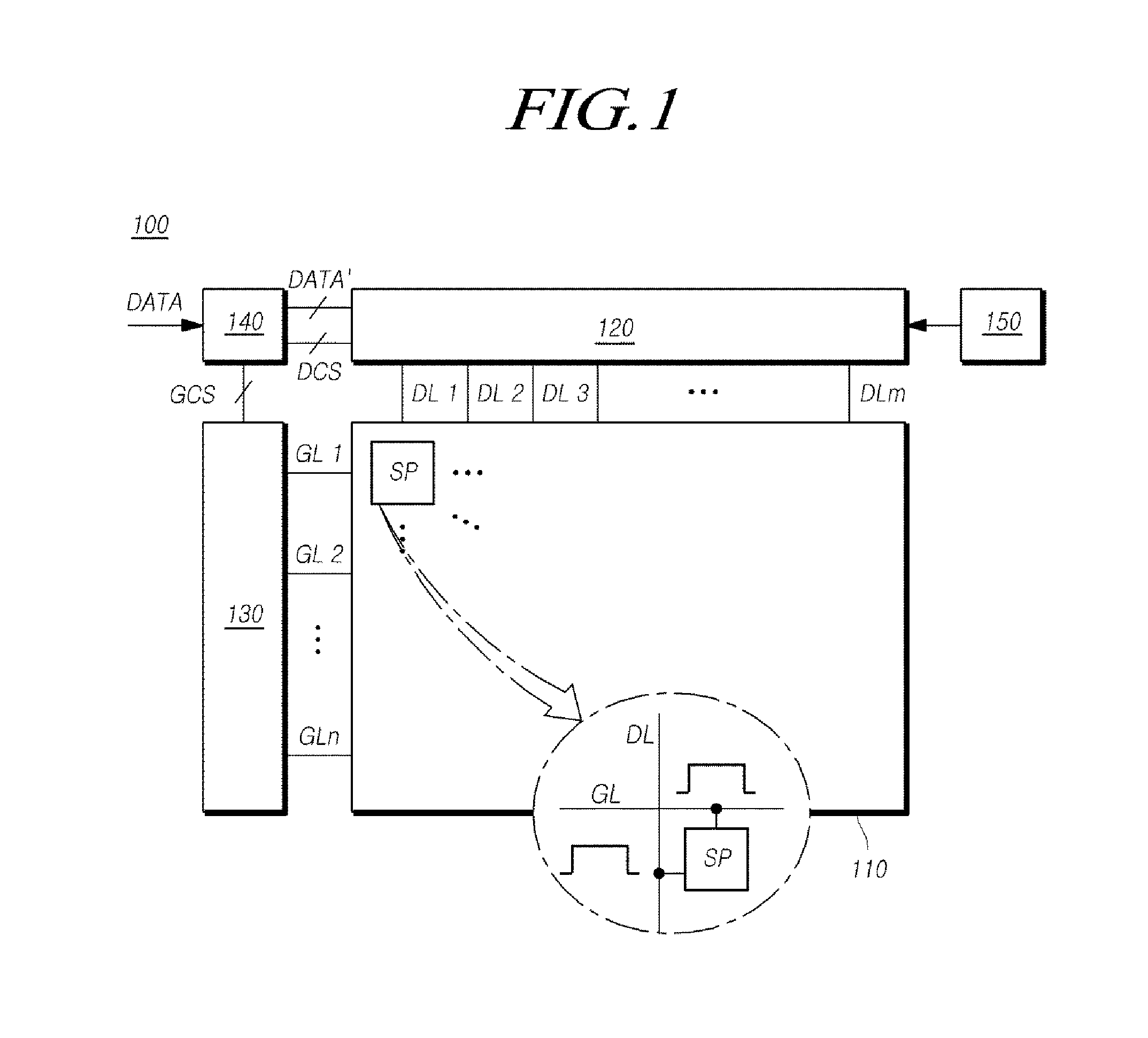
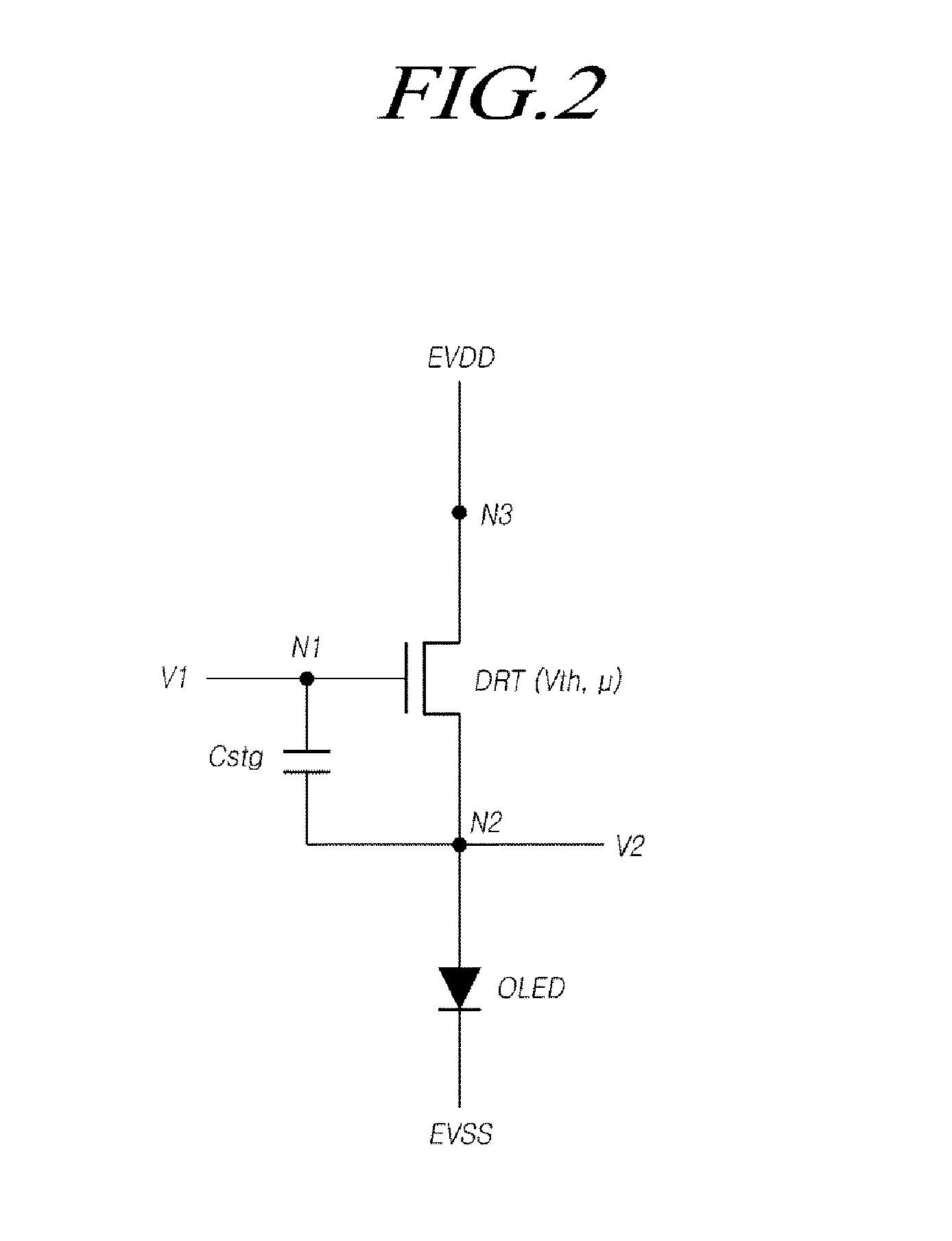
An OLED display device includes an OLED display panel on which subpixels are disposed, a gamma reference voltage supply circuit supplying gamma reference voltages that are variable during driving and when sensing a threshold voltage, and a data driver supplying data voltages based on the gamma reference voltages to data lines. The data driver senses a voltage of a sensing node within each of the subpixels in sensing mode. A timing controller controls the data driver, and performs a compensation process based on the voltage sensed by the data driver.

Description

CROSS REFERENCE TO RELATED APPLICATION[0001]This application claims priority from and the benefit under 35 U.S.C. §119(a) of Korean Patent Application Number 10-2014-0195605 filed on Dec. 31, 2014, which is hereby incorporated by reference for all purposes as if fully set forth herein.BACKGROUND OF THE INVENTION[0002]1. Field of the Invention[0003]The present invention relates to an organic light-emitting diode (OLED) display device that displays images.[0004]2. Description of Related Art[0005]Organic light-emitting diode (OLED) display devices have recently been prominent as next generation display devices. Such OLED display devices have some advantages, such as relatively fast response speeds, high contrast ratios, high light emitting efficiency, high luminance levels, and wide viewing angles, since OLEDs able to emit light by themselves are used therein.[0006]Such an OLED display device includes subpixels arranged in the shape of a matrix, each of the subpixels including an OLED,...

Claims


Application Information

Patent Timeline
IPC IPC(8): G09G3/32
CPCG09G3/3258G09G2320/0673G09G2300/0439G09G2320/0233G09G2310/0286G09G2310/027G09G2310/08G09G3/3291G09G3/3233G09G2320/0276G09G2320/0295G09G2320/045G09G2340/0428H10K59/35H10K59/131H10K71/00
Inventor MIWA, KOICHIHAN, SEONG-EOKLEE, JUNGHYUNJO, YONGHAN
Owner LG DISPLAY CO LTD
Learn More