Optimization of a battery driven ultrasound device

a battery-driven ultrasound and ultrasound technology, applied in the field of optimizing a battery-driven ultrasound device, can solve the problem of reducing the lifespan of the smartphone battery

Inactive Publication Date: 2016-06-30
GENERAL ELECTRIC CO
View PDF8 Cites 2 Cited by
  • Summary
  • Abstract
  • Description
  • Claims
  • Application Information

AI Technical Summary

Benefits of technology

[0004]Another embodiment relates to a handheld ultrasound system. The handheld ultrasound system includes a Smartphone unit, an acquisition unit, and a main battery. The Smartphone unit includes a Smartphone battery. The acqu

Problems solved by technology

When the ultrasound system includes a Smartphone, frequent charging and discharg

Method used


Image

  • Optimization of a battery driven ultrasound device
  • Optimization of a battery driven ultrasound device
  • Optimization of a battery driven ultrasound device

Examples


Embodiment Construction

[0012]In the following detailed description, reference is made to the accompanying drawings that form a part hereof, and in which is shown by way of illustration specific embodiments that may be practiced. These embodiments are described in sufficient detail to enable those skilled in the art to practice the embodiments, and it is to be understood that other embodiments may be utilized and that logical, mechanical, electrical and other changes may be made without departing from the scope of the embodiments. The following detailed description is, therefore, not to be taken as limiting the scope of the invention.

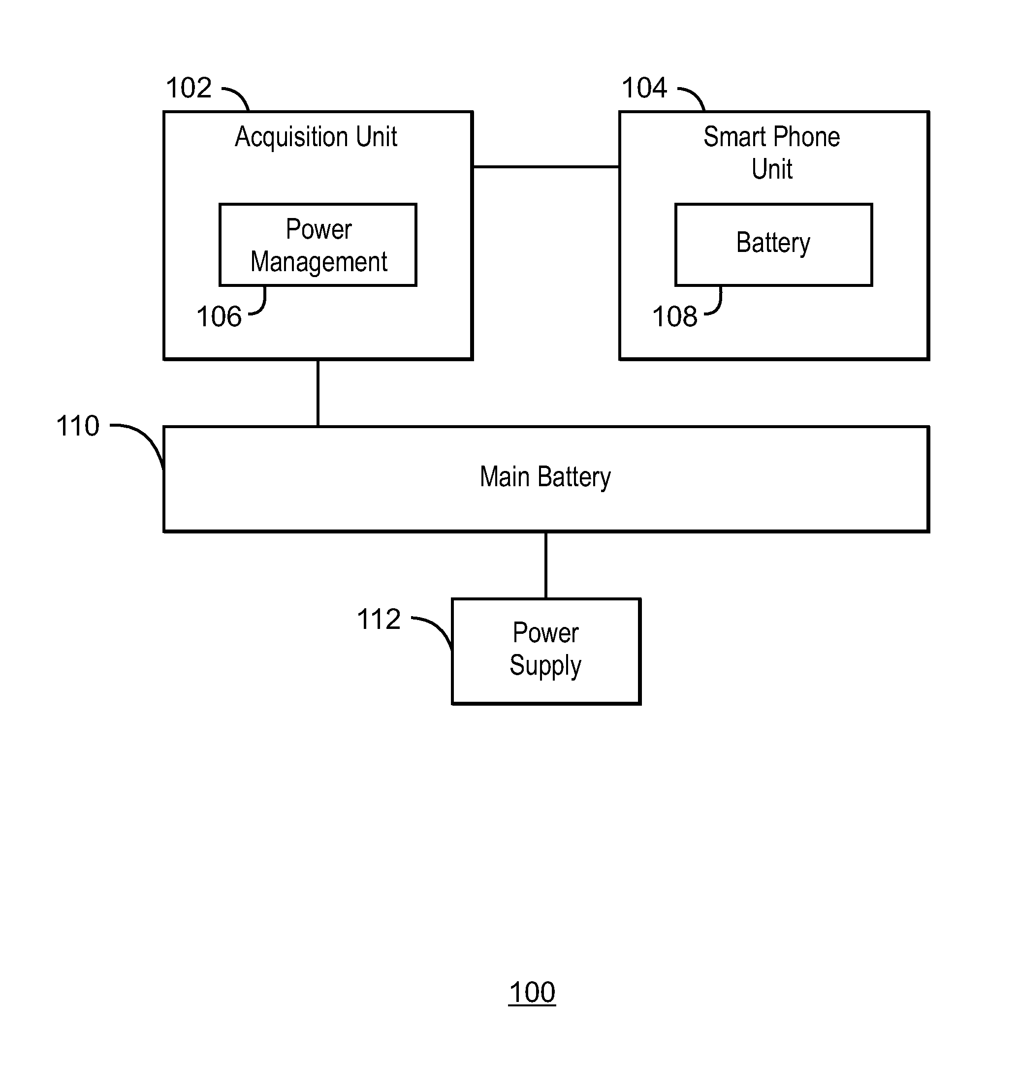
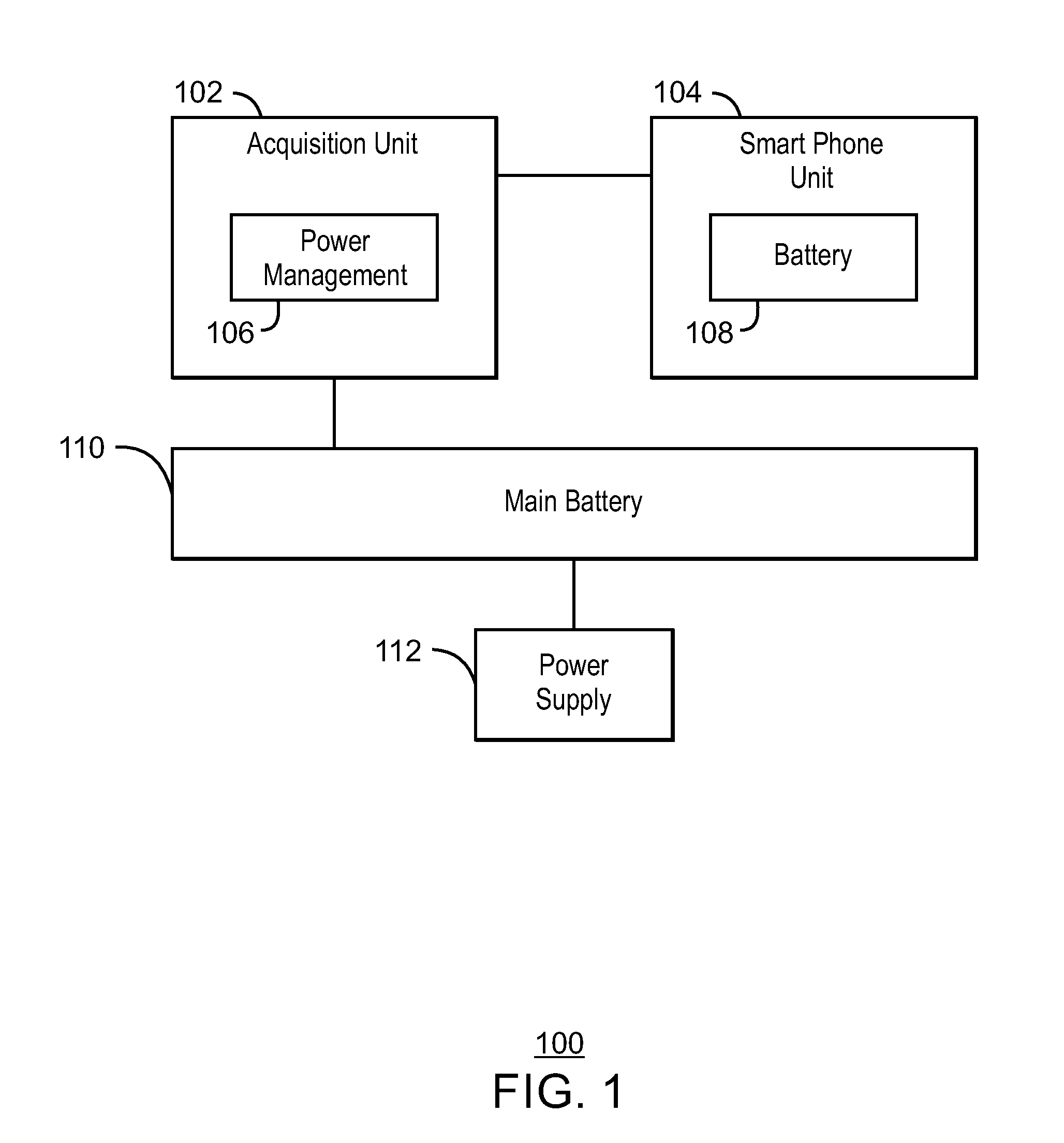
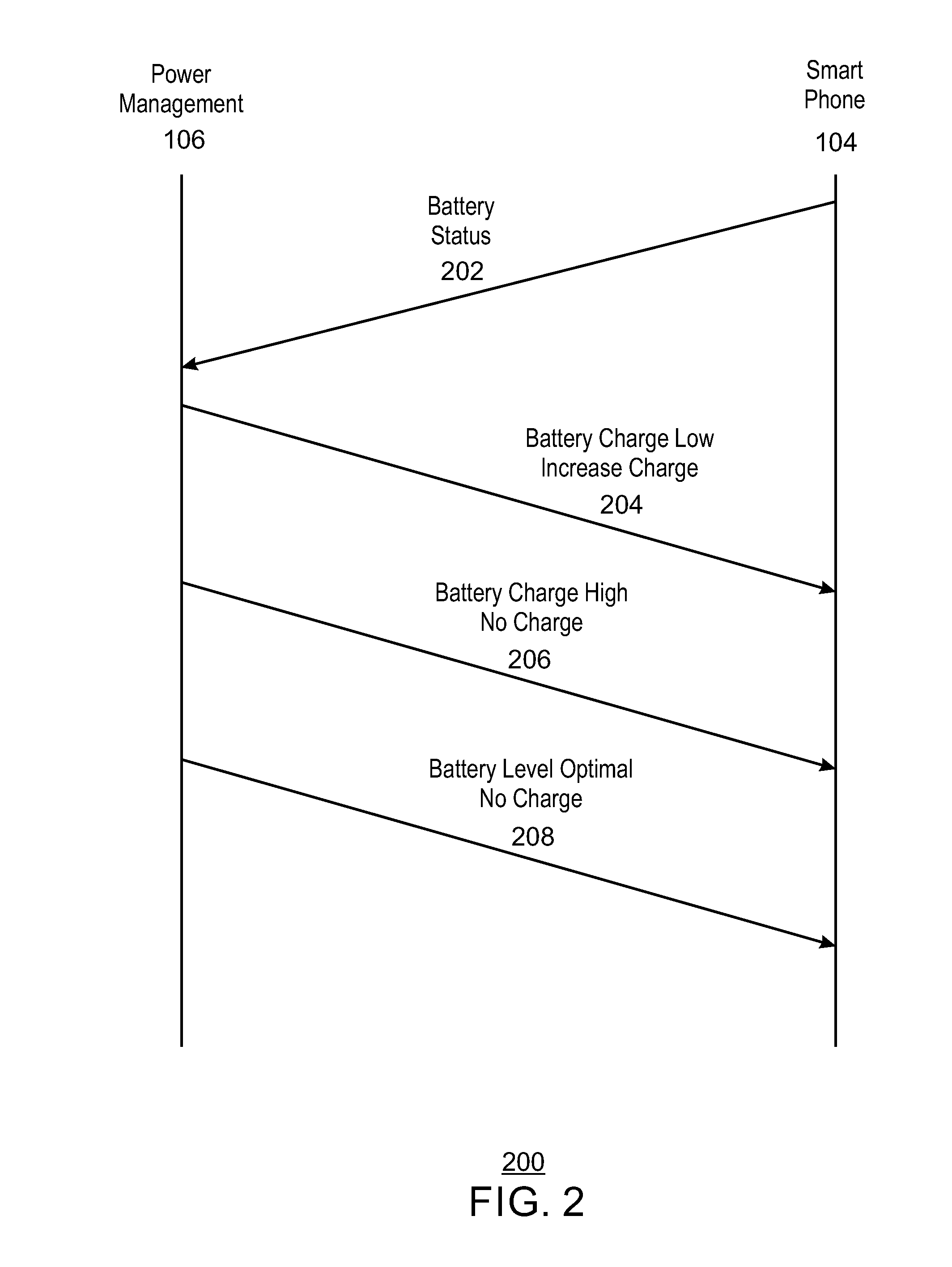
[0013]Handheld ultrasound devices are designed to be charged and discharged may times over a life cycle. Many factors can affect the life cycle of a battery, including but not limited to ambient temperature, amount of charge (i.e., charging to 40% of capacity vs. 80% of capacity), and operating temperature. Thus, power management includes managing battery features in order to ...


PUM


Abstract

An apparatus is described herein. The apparatus includes a first battery and a main battery. The first battery is a phone battery. The main battery is a battery of a handheld ultrasound system and the main battery is to maintain a charge of the first battery at an optimal charge level.

Description

BACKGROUND OF THE INVENTION[0001]Portable ultrasound systems often include rechargeable batteries for ease of portability. Portable ultrasound systems enable ultrasound data to be quickly accessible in a variety of situations. For example, portable ultrasound systems can add more information to routine examinations where a traditional ultrasound device is not present. Moreover, portable ultrasound systems are useful in emergency situations, and can provide valuable information to medical service providers, such as emergency medical personnel.[0002]Handheld ultrasound systems offer increased portability and maneuverability when compared to portable ultrasound systems. Often, handheld systems include one or more rechargeable batteries. As a result, the battery of the portable ultrasound system can be charged as necessary. When the ultrasound system includes a Smartphone, frequent charging and discharging of the Smartphone battery can reduce the lifespan of the Smartphone battery.SUMMA...

Claims


Application Information

Patent Timeline
IPC IPC(8): H02J7/00A61B8/00G01R31/36
CPCH02J7/0054A61B8/56A61B8/4427G01R31/3606H02J7/342H02J2310/23G01R31/382H02J7/00
Inventor SANDVIK, TRONDBJAERUM, STEINAR
Owner GENERAL ELECTRIC CO
Why Eureka
Try Eureka