Capsule multi-piercer with assembly means

Inactive Publication Date: 2016-07-14
NESTEC SA
View PDF0 Cites 5 Cited by
  • Summary
  • Abstract
  • Description
  • Claims
  • Application Information

AI Technical Summary

Benefits of technology

[0031]The risk of crushing the capsule when the openings are formed by the blades can be minimized by arranging the piercing device so th

Problems solved by technology

The passage formed between the blade and these boundaries may be too small for allowing the desired flow of liquid into or out of the capsule.
As a result, the flow along the capsule may be too small, or the capsule may be torn in an unwanted manner about the boundaries (in the case of a pressurized outflow of liquid from the capsule) or the capsule may be crushed (in the case of a pressurized inflow or attempted inflow of liquid into the capsule).
Such a large through-opening however also weakens the mechanical strength of the blade.
This may become an issues over time, especially when harder capsules are used that are not easily pierced by the blade.
Such an added constraint on the blade during piercing may of course lead to an early failure of a blade with a through-opening.
One problem encountered with prior art piercing, in particular piercing of capsule prior to any pressure rise within the capsule, resides in an insufficient circulation of fluid into the c

Method used


Image

  • Capsule multi-piercer with assembly means
  • Capsule multi-piercer with assembly means
  • Capsule multi-piercer with assembly means

Examples


Embodiment Construction

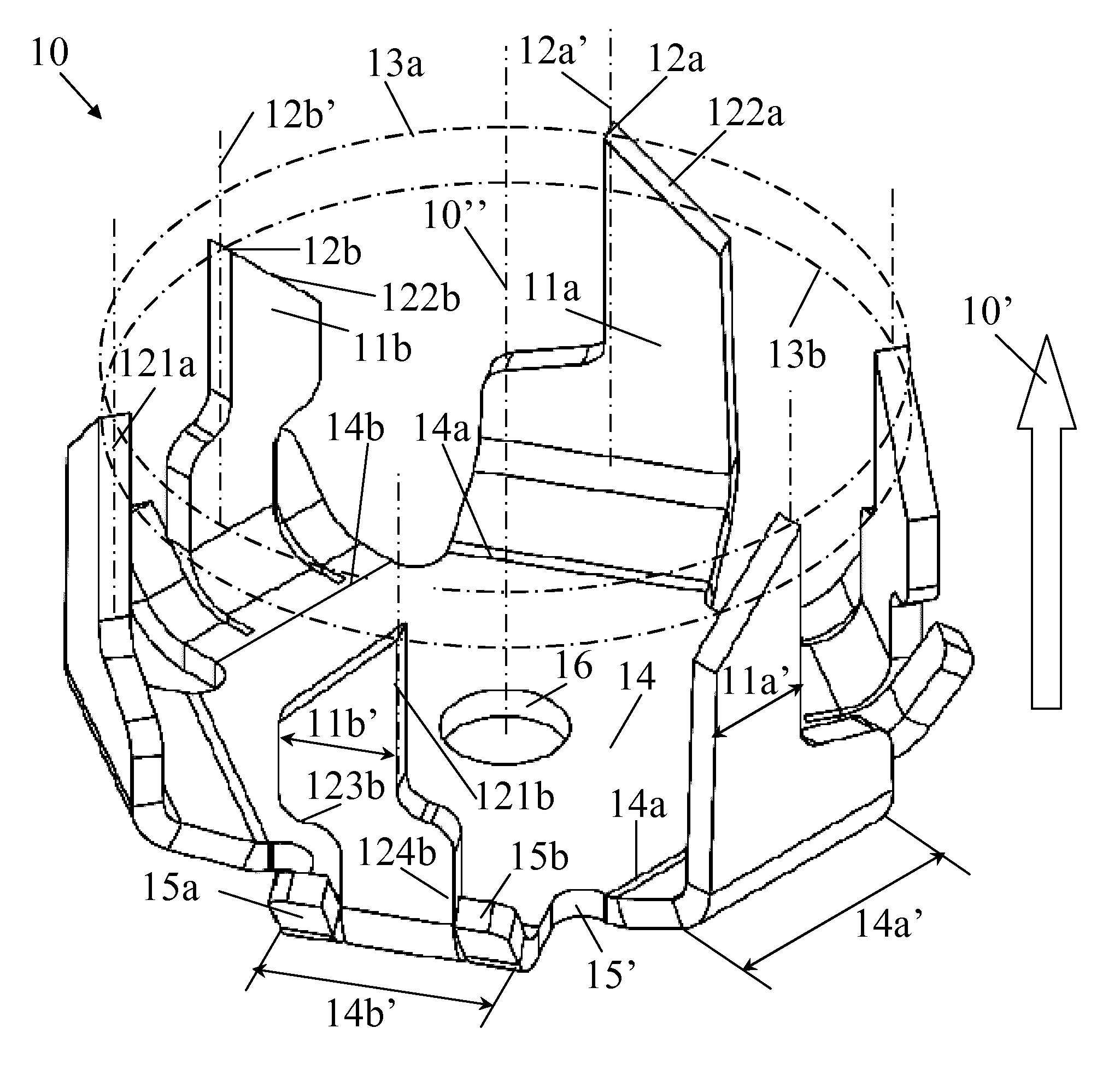
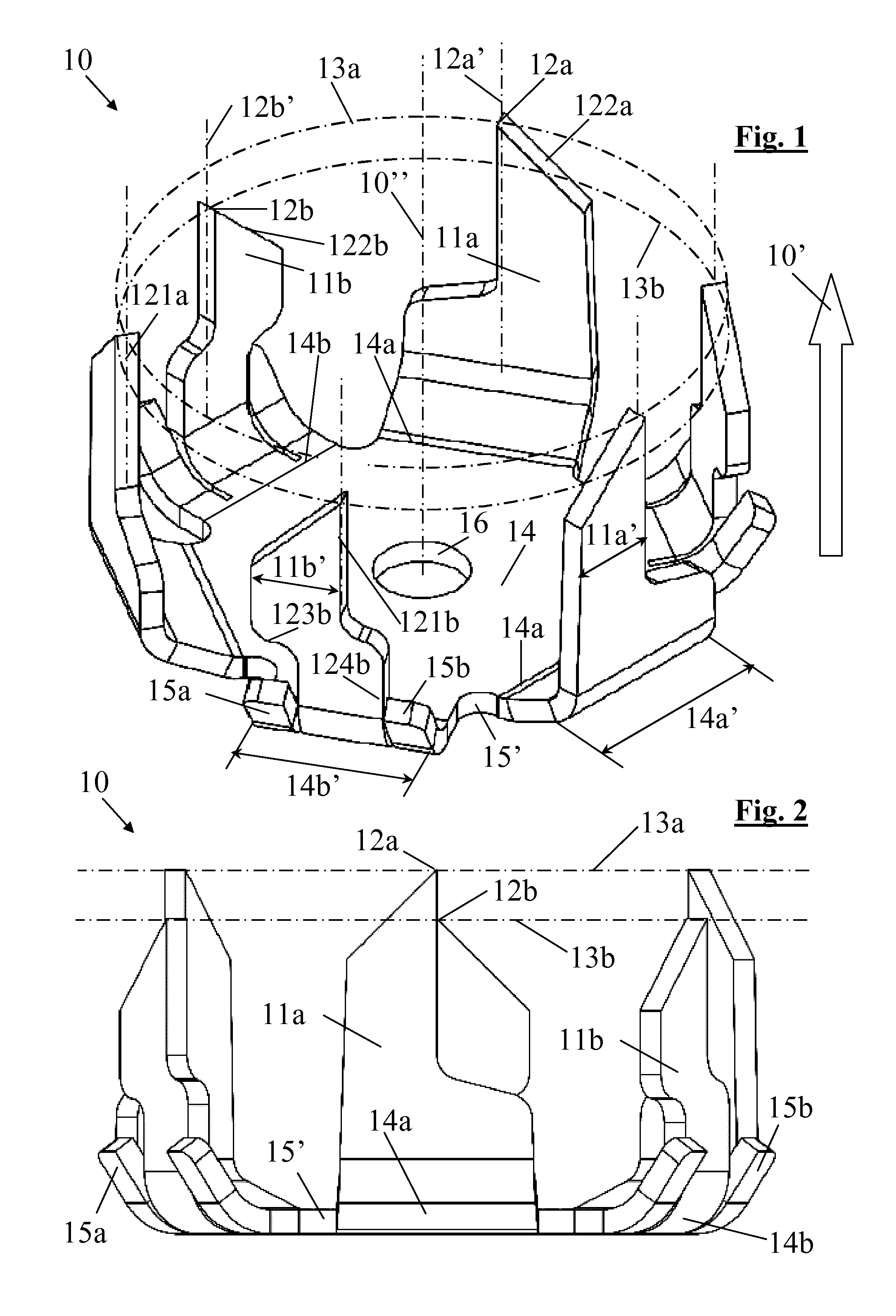
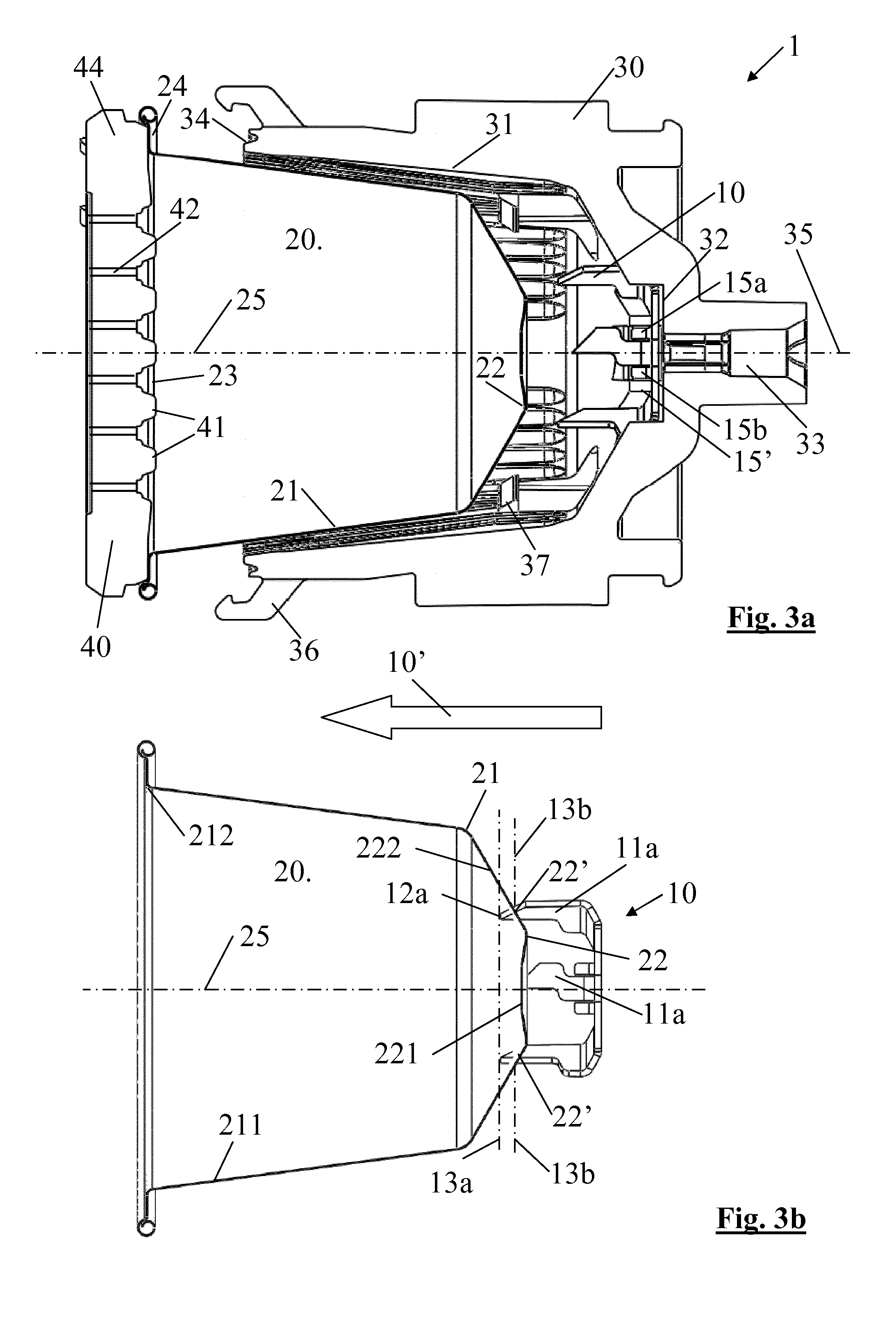
[0064]An example of an extraction unit 1 and its cooperation with a capsule 20 according to the invention is generally illustrated in FIGS. 1 to 3d. An extraction unit 1 having capsule receivers 30,40 and a piercing device 10 with a cooperating capsule 20 are shown in FIGS. 3a and 3d. Piercing device 10 is illustrated in detail in FIGS. 1 and 2. A piercing sequence of a capsule 20 is shown in FIGS. 3a to 3d. Another example according to the invention of a piercing device 10 in an extraction unit 1 is illustrated in FIGS. 4 and 4a.

[0065]A comparative Example of a piercing device 10a which can be mounted in a receiver 30 and replaced by a piercing device 10 according to the invention is illustrated in FIG. 5.

[0066]Prior art piercing device 10a comprises three blades extending from a base 14 and spaced apart from one another by protruding fastening arrangements, such as protruding spring plates 15, for fastening piercing device 10a to capsule receiver 30 of the type shown in FIGS. 3a ...


PUM


Abstract

An extraction unit (1) has a piercing device (10) for piercing a capsule (20). The piercing device includes: a base (14) with peripheral sections, such as generally straight peripheral sections (14a, 14b, 14c1, 14c2); a plurality of blades (11a, 11b, 11c) that protrude from the base along a longitudinal direction (12a′, 12b′, 12c′), each blade extending laterally generally along one of the peripheral sections (14a, 14b, 14c1); and a plurality of assembly members (15a, 15b, 15c), each assembly member (15a, 15b, 15c) extending and protruding from one of the peripheral sections (14b,14c2). At least one assembly member (15a, 15c) of said assembly members (15a, 15b, 15c) is located at least in part generally in the longitudinal direction (12b′, 12c′) under a corresponding blade (11b, 11c).

Description

FIELD OF THE INVENTION[0001]The present invention relates to a device for piercing the capsule in a capsule extraction unit, to a combination of such extraction unit and a capsule, to the method of piercing the capsule and to the use of a capsule for such piercing.[0002]For the purpose of the present description, a “beverage” is meant to include any human-consumable liquid substance, such as tea, coffee, hot or cold chocolate, milk, soup, baby food, etc . . . . A “capsule” is meant to include any pre-portioned beverage ingredient, such as a flavouring ingredient, within an enclosing packaging of any material, in particular an airtight packaging, e.g. plastic, aluminium, recyclable and / or biodegradable packagings, and of any shape and structure, including soft pods or rigid cartridges containing the ingredient.TECHNICAL BACKGROUND[0003]Certain beverage preparation machines use capsules containing ingredients to be extracted or to be dissolved and / or ingredients that are stored and do...

Claims


Application Information

Patent Timeline
IPC IPC(8): A47J31/40B26F1/00B65D85/804
CPCA47J31/407B26F1/00B65D85/8043A47J31/0673A47J31/3628A47J31/3695B65D85/8049B65D85/8052
Inventor FLICK, JEAN-MARCCOLANTONIO, JEAN-LUC
Owner NESTEC SA
Why Eureka
Try Eureka