

Sink plug arrangement
- Summary
- Abstract
- Description
- Claims
- Application Information
AI Technical Summary
Benefits of technology
Problems solved by technology
Method used
Image

Examples
first embodiment
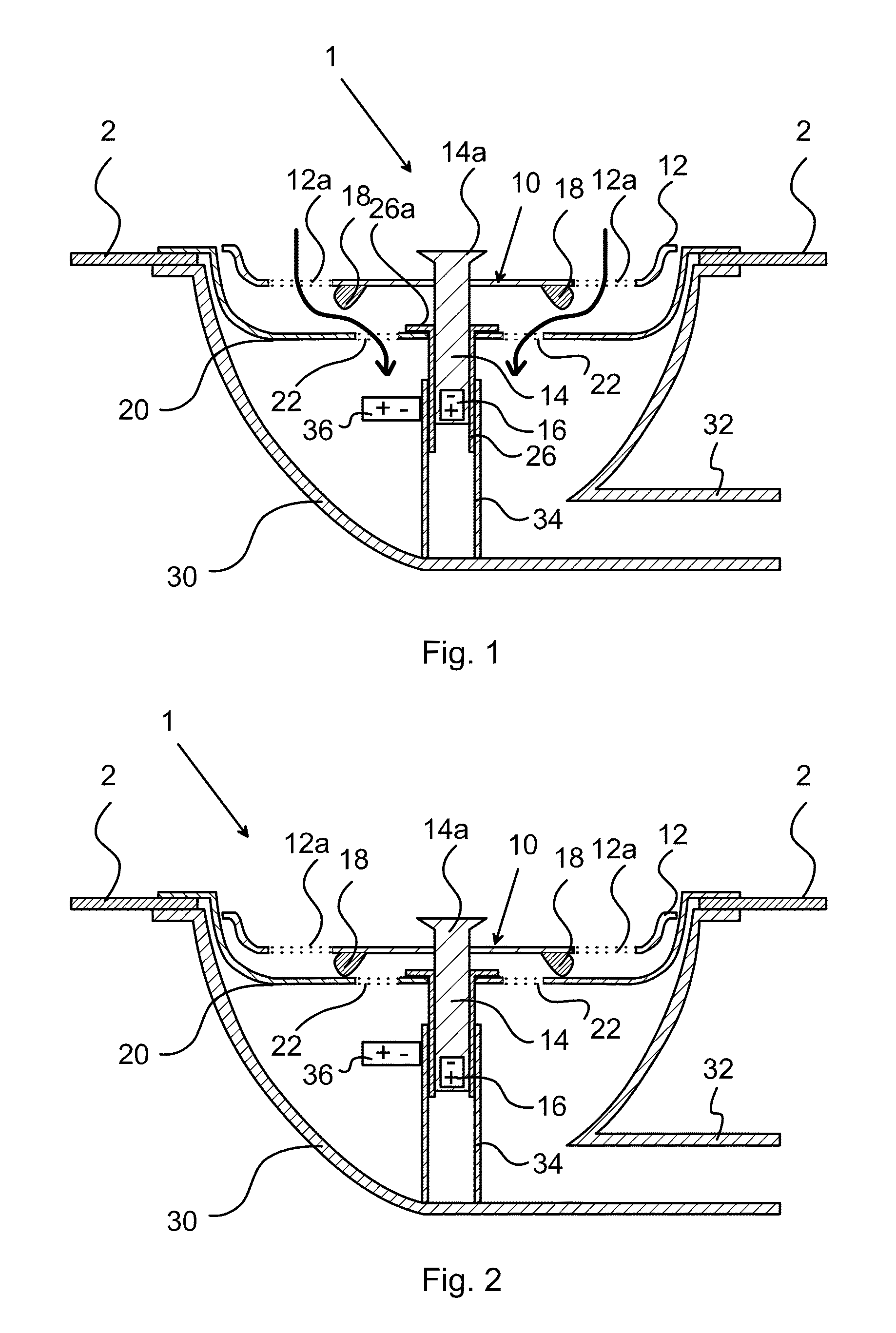
[0025]In FIGS. 1 to 3 a sink plug arrangement according to the invention is shown illustrating the sink plug arrangement, generally designated 1. A sink plug or strainer 10 is a part of the sink plug arrangement 1 and is in FIG. 1 shown in an open state where liquid is allowed to pass, via a strainer basket 20, through a sink outlet 30, which in turn is attached to a drain (not shown).
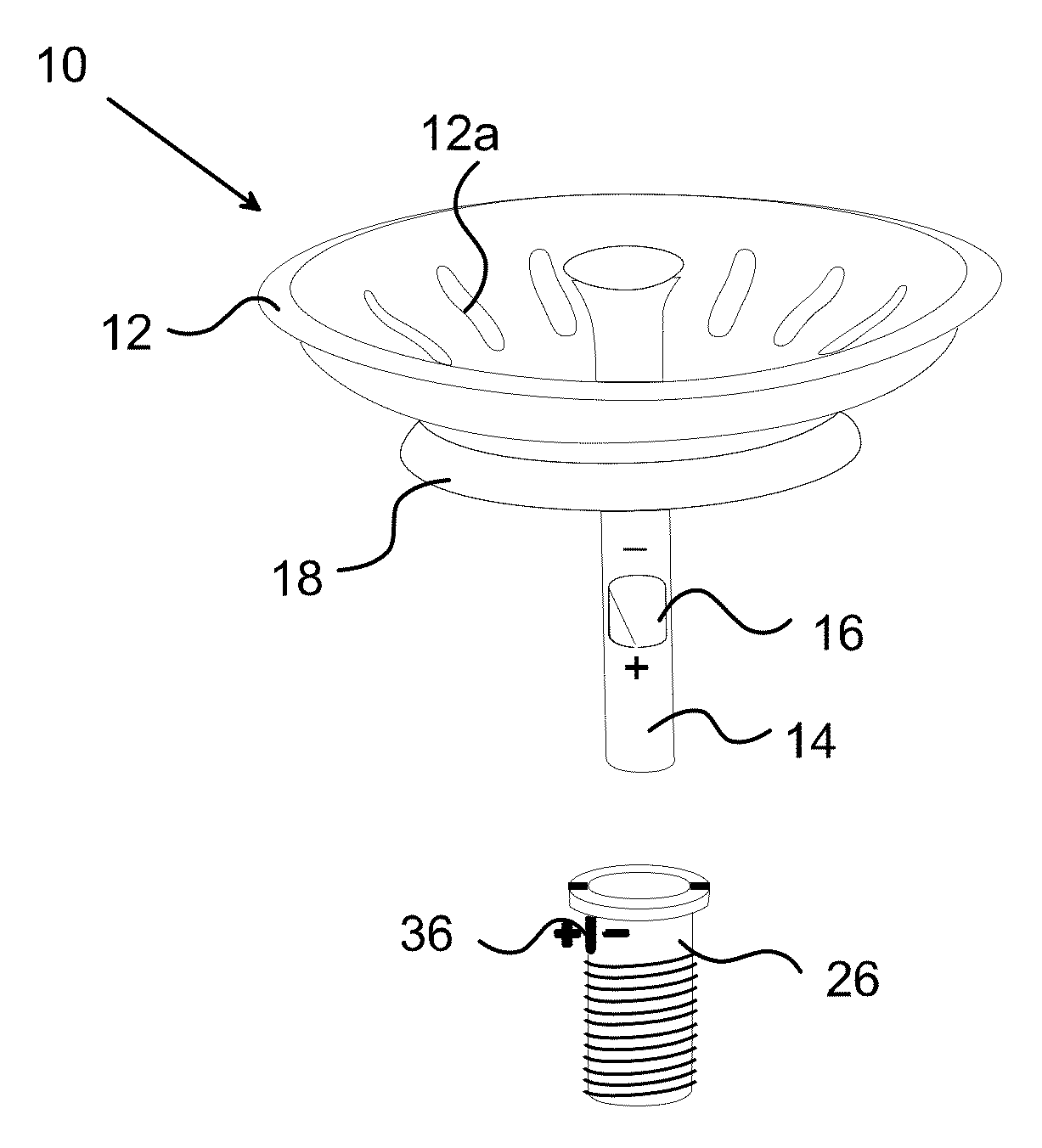
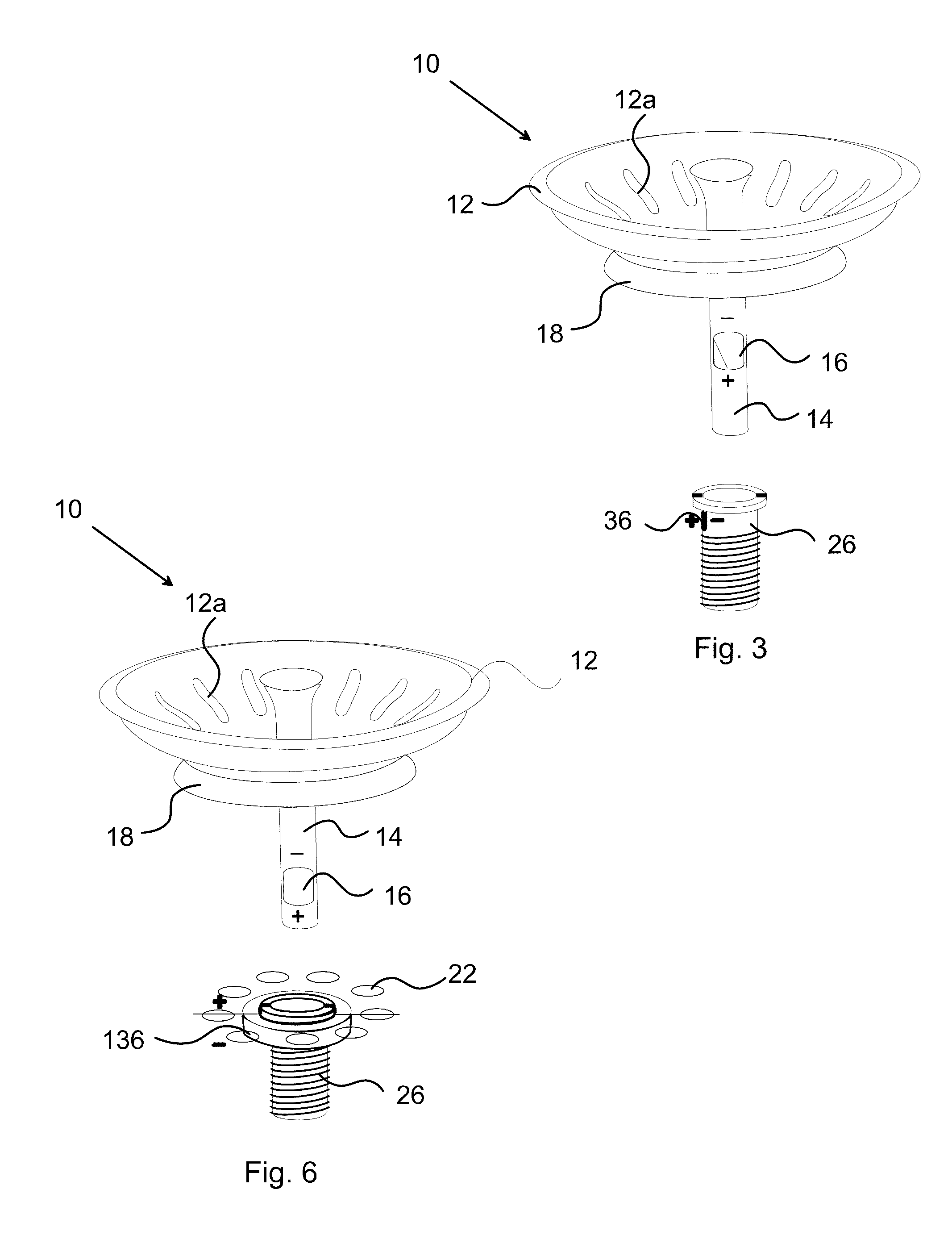
[0026]The strainer 10 comprises a circular sieve 12, see also FIG. 3, provided with a plurality of circumferentially spaced apart holes 12a, shown with dashed lines in FIGS. 1 and 2. A stem 14 is centrally attached to the sieve 12 and is during operation vertically oriented in the sink outlet 30. The upper end portion of the stem is shaped as a knob 14a adapted to be gripped by a user of the sink plug arrangement. A first magnet 16, preferably a permanent magnet, is provided in the stem close to the lower end thereof. The first magnet 16 is vertically oriented with in the described example the negative...
second embodiment
[0034]FIG. 4 shows a sink plug arrangement, generally designated 101, wherein the strainer 10 in an upper open position. In this embodiment this maintained by the repellant force between the first permanent magnet 16 provided in the stem 14 of the strainer 10 and the second permanent magnet 136 provided as a collar around the cylinder 26 and thereby around the stem 14. In a sense, the strainer 10 levitates on the magnetic field created by the circular permanent magnet 136.
[0035]When the strainer 10 is pushed downward by a user, for example by exerting a downward force on the grip 14a, the first permanent magnet 16 passes through the second permanent magnet 136. When the first permanent magnet 16 is below the second permanent magnet 136, as shown in FIG. 5, the repellant force between the magnets forces the strainer 10 downward to the lower end position shown in FIG. 5. The strainer 10 can be returned to its upper open position by a user pulling the grip 14a upward.
[0036]The second e...
PUM
 Abstract
Description
Claims
Application Information