Lock body with adjustable strike plate for sliding doors

a technology of adjustable strike plate and lock body, which is applied in the field of lock body, can solve the problems of inconvenient maintenance of user comfort, prone to deflection of dead bolts, and harsh metal sound, and achieves simple joint structure, facilitate fine-tuning of vertical position, and skillful construction

Active Publication Date: 2016-07-21
CHENG QIANYAN
View PDF1 Cites 11 Cited by
  • Summary
  • Abstract
  • Description
  • Claims
  • Application Information

AI Technical Summary

Benefits of technology

[0025]This utility model is skillfully constructed, adopts simple joint structure to effectively solve the problem of fine-tuning the strike box, facilitates fine-tuning of the vertical position of the strike box and brings convenience to the alignment process of the strike box and door lock bolt.
[0026]Accordingly, a primary object of the present invention is to provide a lock body for sliding doors which avoids making excessive noise during operation.
[0027]Another object of the present invention is to provide a system and method for adjusting a strike plate relative to a lock body to allow the lock body to precisely fit in a door frame for easy and reliable operation of a sliding door.
[0028]Another object of the present invention is to provide a lock body for a sliding door which is easy to use, even by disabled individuals and provides reliable operation to lock and unlock the sliding door.

Problems solved by technology

However, applicant has found in practice that existing lock bodies easily cause stuck hooks due to their inability to automatically reset during use and that the dead bolt is prone to deflection after long-term use.
In addition, the lock body used in existing sliding doors is usually provided with a popable draw ring, but as the lock body is made of metal, a harsh metal sound will be produced when the draw ring pops up, which is inconducive to maintaining user comfort.
After search, it is discovered that a Chinese utility model patent titled “An Electric Lock for Sliding Doors” (Application Number 201020119517X and authorized Publication Number CN201661139U) adopts the structure of combined sliding of sliding column and chute to achieve hook stretching and retracting, but a big force is required during the process of thrusting and pulling the hook, which will cause serious wear to sliding column and chute under long-term contact and friction.
The applicant found in practice that, on the one hand, it is very difficult to align the centerline of the strike box with that of the door lock bolt during installation; on the other hand, the door body will droop due to the door weight or other factors after use for some time, leading to the deviation between the centerline of door lock bolt and that of the strike box.
However, the existing structure of strike plate and strike box assembly, coupled with the impossibility of freely adjusting the position of fastening hole in a door frame after the fastening hole has been set, makes it impossible to fine-tune the position of the strike box after it is properly affixed on the door frame.
Although it is a small problem, it cannot be effectively solved.
After search, the existing technologies represented by a Chinese utility model titled “A Mute Strike Box” (Application Number 201320860057.X and authorized Publication Number CN203640400U) have not made effective improvements with respect to the above problem.

Method used


Image

  • Lock body with adjustable strike plate for sliding doors
  • Lock body with adjustable strike plate for sliding doors
  • Lock body with adjustable strike plate for sliding doors

Examples


Embodiment Construction

[0039]Further details of this invention are given by referring to the drawings combined with embodiments in the following pages, but this invention is not limited to the given embodiments.

[0040]Lock Body Embodiment

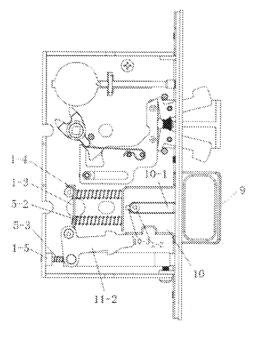
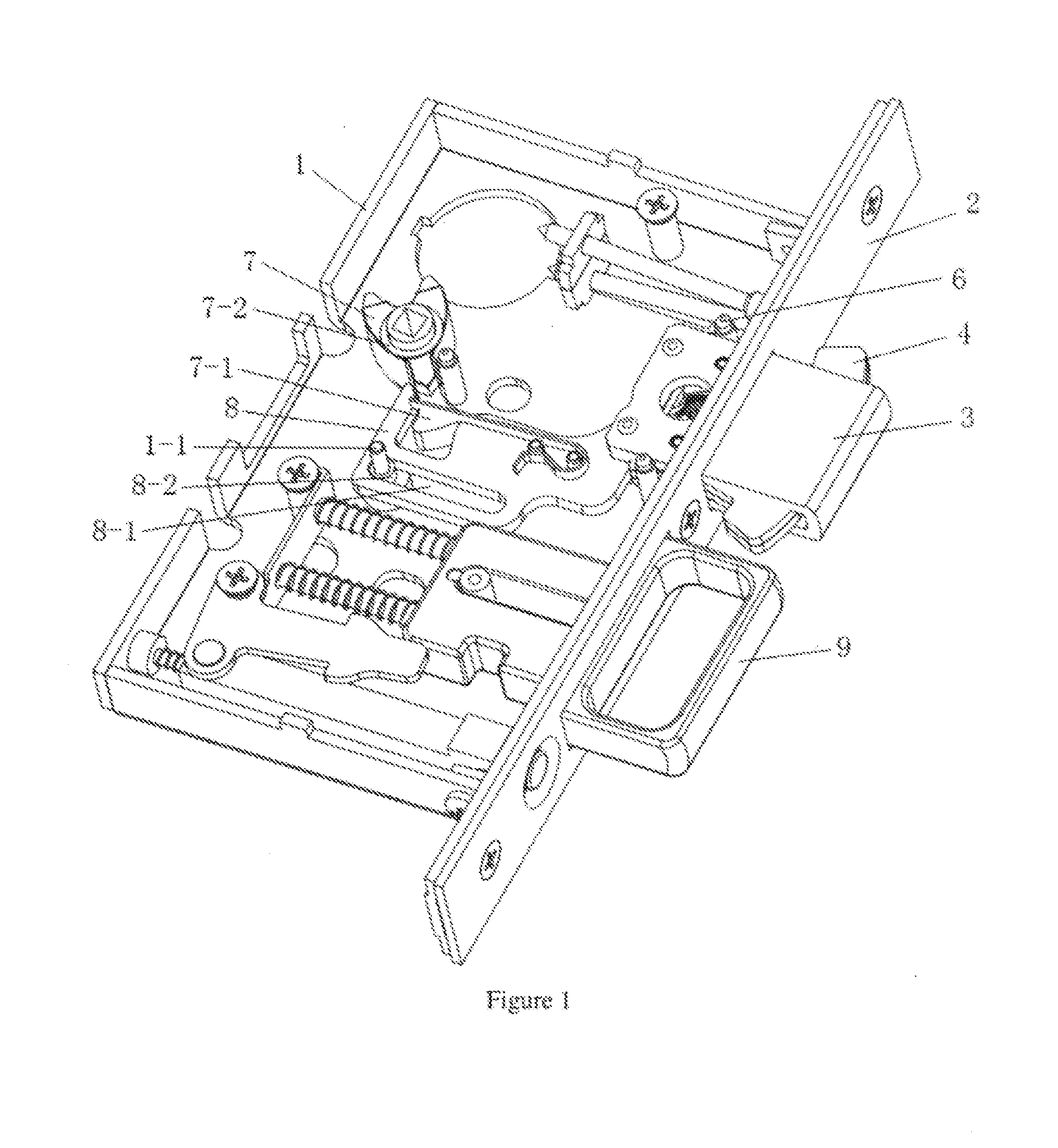
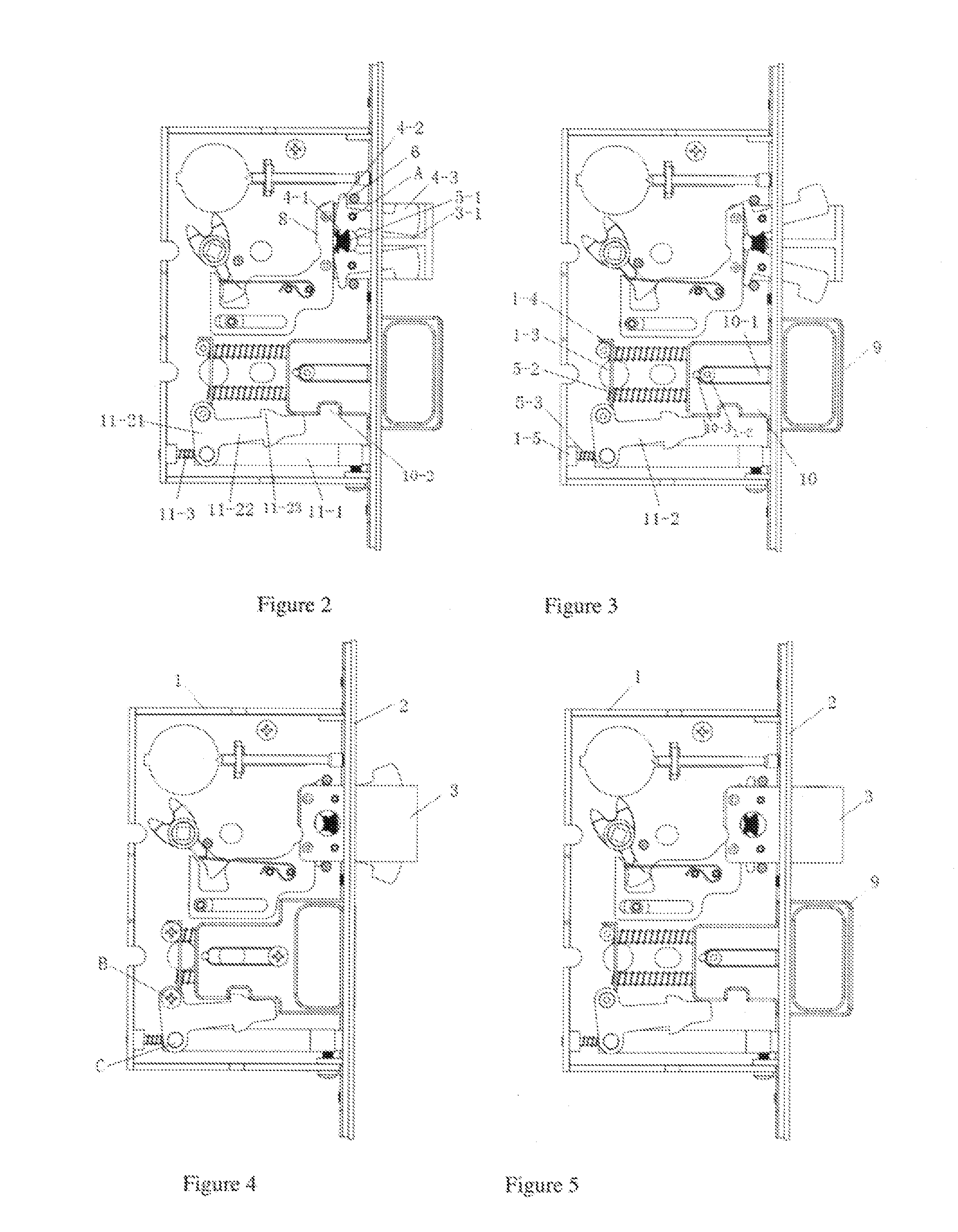
[0041]As shown in FIG. 1 to FIG. 9, the handle lock body for sliding doors in this embodiment, comprising a lock shell 1 and a side panel 2, the side panel 2 is permanently connected with the lock shell 1; a dead bolt 3 is provided in the lock shell 1 to be drive-jointed with the drive mechanism, the side panel 2 has a through hole for the access of dead bolt 3; the dead bolt 3 has a hollow rectangular shell; two hooks 4 are symmetrically set along the access direction of dead bolt 3 in the dead bolt 3 shell; the hooks 4 are hinged with dead bolt 3 shell at the hinge points A which are located between the two ends of the hooks 4; an elastomer 5-1 is set between the hooks 4 where the extending direction intersects the access direction of dead bolt 3; limit posts 6 are provi...


PUM


Abstract

A dead bolt is provided in a lock shell to be drive-jointed with a drive mechanism. Two hooks are symmetrically set along an access direction of dead bolt in the shell. The hooks are hinged with an elastomer therebetween. A draw ring is set to keep mute upon popup under the action of anti-collision mute strip. A strike plate and strike box assembly have a panel with an elongate groove on at least one end thereof. The elongate groove has a set of slots on at least one side thereof. The strike plate is provided with a fastening hole on each end. The fastening hole has a sidewall extending above the plane of the strike plate with a clip bar at a position able to fit into a corresponding slot in the elongate groove. The clip bar joints the corresponding slot to facilitate alignment adjustability.

Description

CROSS-REFERENCE TO RELATED APPLICATIONS[0001]This application claims benefit under Title 35, United States Code §119(e) of U.S. Provisional Application No. 62 / 105,469 filed on Jan. 20, 2015.FIELD OF THE INVENTION[0002]This utility model relates to a lock body, to be specific, a handle lock body for sliding doors. It belongs to the technical field of locks and lock accessories. This utility model also relates to a kind of assembly for door locks, to be specific, a kind of strike plate and strike box assembly for door locks which is adjustable to improve fit with a door frame.BACKGROUND OF THE INVENTION[0003]Most lock bodies used in existing sliding doors have a dead bolt structure, and to enhance tamper resistance, most of them are provided with hooks extending towards both sides of the dead bolt and the contact of hooks with a lock body panel is used to achieve reset. However, applicant has found in practice that existing lock bodies easily cause stuck hooks due to their inability t...

Claims


Application Information

Patent Timeline
Patent Type & Authority Applications(United States)
IPC IPC(8): E05C5/02E05B15/02E05B63/08
CPCE05C5/02E05B15/024E05B15/0205E05B63/08E05B15/0245E05B15/102E05B65/0858
Inventor CHENG, QIANYAN
Owner CHENG QIANYAN
Why Eureka
Try Eureka