Compact and firm single-degree-of-freedom bionic joint and manufacturing method thereof

A technology of bionic joints and manufacturing methods, applied in the field of robotics, can solve problems such as energy consumption, deformation, tensile resistance, and small torsion resistance, and achieve the effects of improving manufacturing efficiency, reducing manufacturing costs, and high impact resistance

Pending Publication Date: 2020-10-30
蔡世勋
View PDF20 Cites 0 Cited by
  • Summary
  • Abstract
  • Description
  • Claims
  • Application Information

AI Technical Summary

Problems solved by technology

[0009] First, the shaft and bushing bear pressure and tension at the same time. In order to ensure the structural strength, the joint volume is large and the manufacturing cost is high
[0010] Second, for mechanical structures containing multiple joints, such as in robot hands, shoulders, and hip joints, the structure of the joints itself takes up too much space, and the space utilization rate is low. difficulty
[0011] Third, the joints are made of hard materials, and when subjected to external impacts, the local load is large, which easily causes material fatigue and deformation, which in turn causes component failure
[0020] First, some adopt deep ball-socket schemes, which lead to interference between the ball head and the edge of the ball-socket, and the range of joint motion is limited; others adopt shallow ball-socket schemes, and the shape of the connecting parts is sleeve-shaped or sheet-shaped, and the joints are not smooth. Stable, weak tensile strength, large displacement of the joint head, easy to fall out of the joint socket
[0021] Second, soft braided materials or other elastic materials are used to make joint connectors, resulting in poor joint stability and weak joint tensile capacity. There is a large gap in the joint under the condition of bearing tangential force, torsional force and tensile force. poor precision
[0022] Third, use a hard and flexible sheet material, such as a rubber sheet, to make the connector. When the joint rotates, the sheet material bends. This deformation produces a resistive moment, consumes energy, and leads to poor mobility
[0023] Fourth, screws, surface bonding, ring clips, etc. are used to connect and fix the connectors and structural parts, which have low strength, poor tear-off resistance, and poor impact resistance
[0024] Fifth, the large number of parts and many assembly and adjustment steps are not conducive to the adoption of standardized manufacturing processes, resulting in high manufacturing costs and low manufacturing efficiency
[0025] Sixth, the FLLEX Hand bionic manipulator uses rolling joints, which are less resistant to tension and torsion

Method used


Image

  • Compact and firm single-degree-of-freedom bionic joint and manufacturing method thereof
  • Compact and firm single-degree-of-freedom bionic joint and manufacturing method thereof
  • Compact and firm single-degree-of-freedom bionic joint and manufacturing method thereof

Examples


Embodiment 1

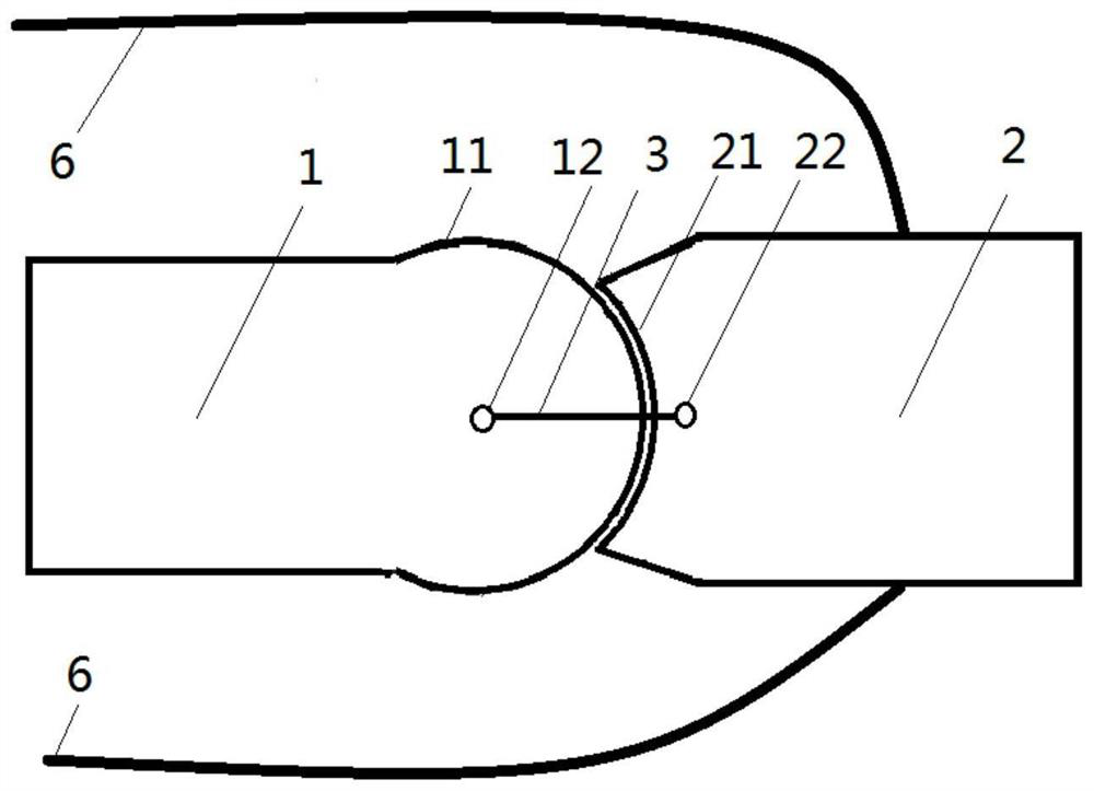
[0059] Reference attached figure 1 , with figure 1 is a side view showing a 1-DOF bionic joint.

[0060] The joint includes a first joint part 1, and the first joint part 1 includes a convex curved surface 11 and a first through hole 12, and the first through hole 12 is located on the central axis of the convex surface.

[0061] The second joint member 2 includes a convex curved surface 21 and a second through hole 22, and the second through hole 22 is near the outer edge of the concave surface. The first joint part 1 and the second joint part 2 are made of light alloy material, and the surfaces of the convex curved surface 11 and the convex curved surface 21 are coated with Teflon material to reduce the coefficient of friction.

[0062] The connecting fibers 3 are arranged symmetrically on both sides of the joint and are made of Kevlar fibers. The Kevlar fiber is pre-soaked with waterproof and UV-resistant resin, and then repeatedly passes through the first through hole 12...

Embodiment 2

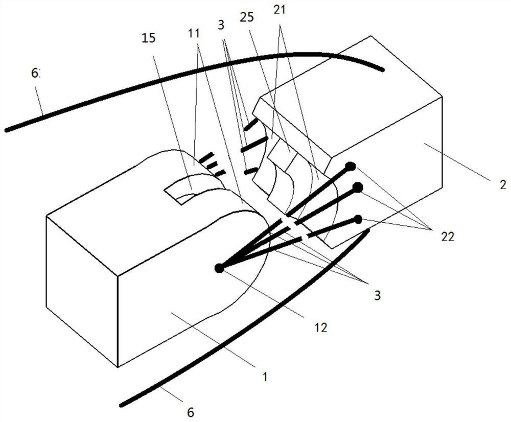
[0066] Reference attached figure 2 , with figure 2 is a 3D exploded view, (connectors cut off), showing a 1DOF joint with internal and external reinforcement.

[0067] The following methods are used to further restrict the range of motion of the joints, and strengthen the joints to increase the strength of the joints.

[0068] The first joint member 1 includes a convex curved surface 11 and a first through hole 12 , and the first through hole 12 is located on the central axis of the convex curved surface 11 .

[0069] The second joint part 2 includes a convex curved surface 21 and a second through hole 22 , and the second through hole 22 is near the edge of the concave curved surface 21 .

[0070] Grooves 15 are provided in the convex curved surface 11 , and ridges 25 are provided in the convex curved surface 21 . The groove 15 is in close contact with the ridge 25 , can slide freely, and can bear the horizontal tangential force of the second joint part 2 .

[0071] The ...

Embodiment 3

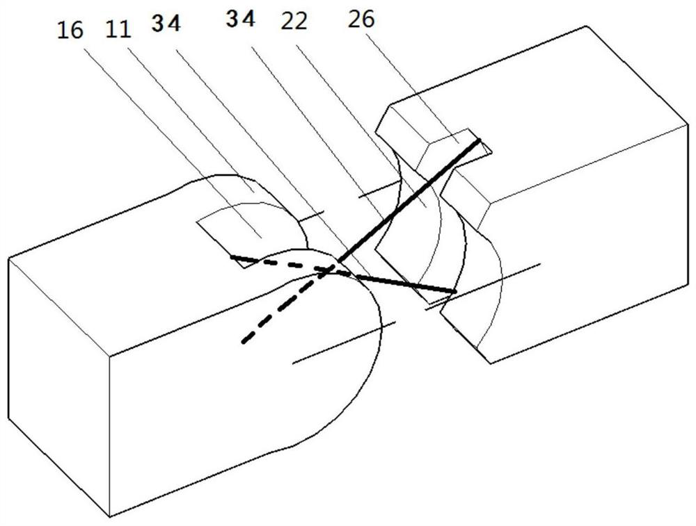
[0075] Reference attached image 3 , respectively remove part of the material at the corresponding positions of the two structural parts to form a depression, and add two connecting lines 34 of intersecting steps in the depression, the blocked connecting line 34 is marked with a dotted line, and the connecting line 34 is connected to the first joint part 1, the second The two joint parts 2 form a cross four-link mechanical structure, and the connecting line 34 is made of aramid fiber.

[0076] The joint adopting this design can withstand large tangential force, and can prevent the joint from translation when it is subjected to tangential force while retaining the rotation function.


PUM


Abstract

The invention discloses a compact and firm single-degree-of-freedom bionic joint and a manufacturing and driving method thereof. The compact and firm single-degree-of-freedom bionic joint comprises atleast one first joint part, a second joint part and a connecting fiber, wherein the end of the first joint part is a convex curved surface, and the end of the second joint part is a concave curved surface matched with the convex curved surface. The compact and firm single-degree-of-freedom bionic joint has the beneficial effects that firstly, the compact and firm single-degree-of-freedom bionic joint is simple in joint structure, small in size, light in weight, high in strength and the like, the impact resistance is high, and the stress of a connecting piece is reduced when the joint is bent;and secondly, the compact and firm single-degree-of-freedom bionic joint is small in gap and high in motion precision under the stress condition, meanwhile, the whole bionic joint is convenient to manufacture through an automatic process, the manufacturing efficiency is improved, and the manufacturing cost is reduced.

Description

technical field [0001] The invention relates to the technical field of robots, in particular to a compact and firm single-degree-of-freedom bionic joint and its manufacturing and driving methods. Background technique [0002] A joint is a common part in a mechanical structure. Its basic functions include: bearing radial and tangential forces, including tensile, compressive and torsional forces; limiting the degree of freedom of mechanical motion, that is, limiting the direction and range of motion. [0003] The existing sleeve-type joint adopts a rigid shaft and a sleeve as a design scheme, and the joint has good stability and high motion precision. For example: [0004] Patentee DISNEY ENTERPRISES, INC.'s invention "ROBOT HAND WITH HUMAN-LIKEFINGERS" (US20100259057A1); [0005] Patentee GM Global Technology Operations LLC's invention "robotic thumbassembly" (US8424941); [0006] The patentee SQUSE Inc.'s invention "finger mechanism, robot hand and robot hand controlling ...

Claims


Application Information

Patent Timeline
Patent Type & Authority Applications(China)
IPC IPC(8): B25J17/02
CPCB25J17/02
Inventor 蔡世勋
Owner 蔡世勋
Why Eureka
Try Eureka