Hinge type robot joint

A robot joint and hinge technology, applied in the field of robots, can solve the problems of complex structure, bloated wrist joint structure, large volume, etc., and achieve the effect of simplifying the joint structure, small transmission viscous resistance, and small inertia

Active Publication Date: 2020-06-16
SHENYANG SIASUN ROBOT & AUTOMATION
View PDF4 Cites 0 Cited by
  • Summary
  • Abstract
  • Description
  • Claims
  • Application Information

AI Technical Summary

Problems solved by technology

Existing industrial robots have complex structures, need to rely on precision reducers, bloated wrist joints, and large volumes

Method used


Image

  • Hinge type robot joint
  • Hinge type robot joint
  • Hinge type robot joint

Examples


Embodiment Construction

[0023] In order to make the object, technical solution and advantages of the present invention clearer, the present invention will be described in detail below in conjunction with the accompanying drawings and specific embodiments.

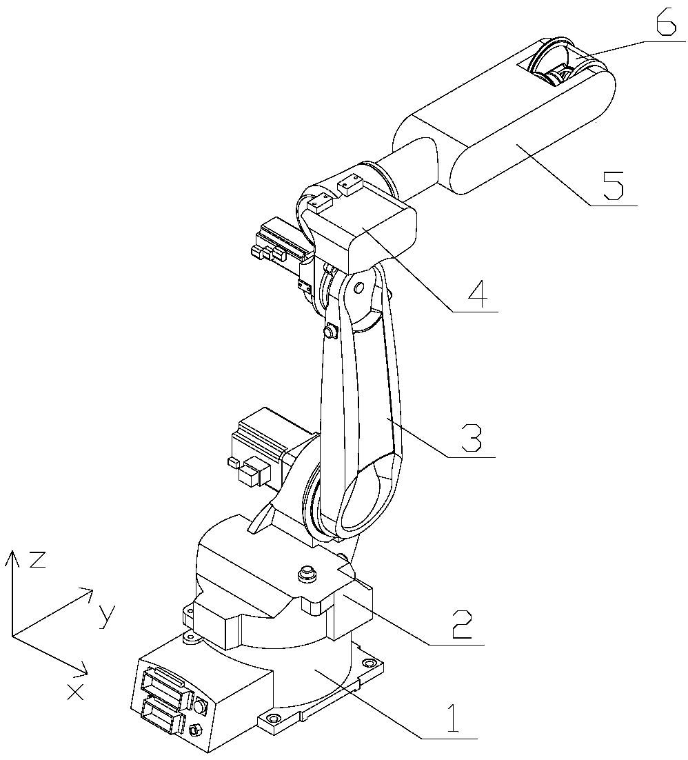
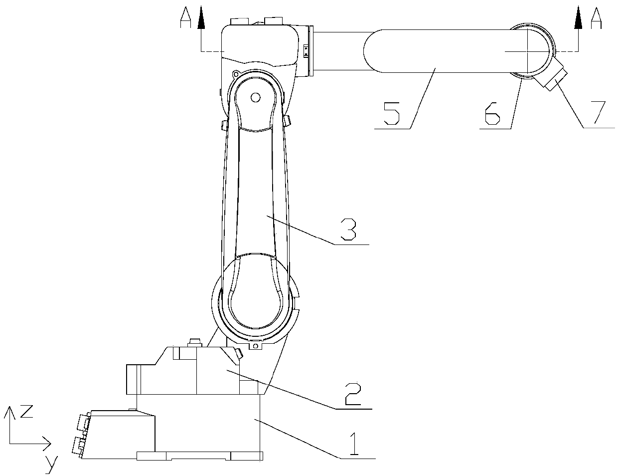
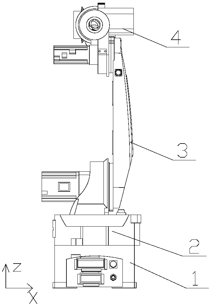
[0024] Such as Figure 1-4 As shown, a hinged robot joint provided by the present invention includes a base 1, a waist seat 2, a large arm 3, a three-axis drive assembly 4, a small arm 5, a wrist shaft assembly 6 and an end flange 7, wherein the waist seat 2 It is arranged on the base 1 and is connected to the base 1 in rotation. One end of the big arm 3 is connected to the waist seat 2 in rotation, the other end is connected to the three-axis drive assembly 4 in rotation, and one end of the small arm 5 is connected to the three-axis drive assembly 4 in rotation. The other end is rotatably connected to the wrist shaft assembly 6, and the end flange 7 is rotatably connected to the wrist shaft assembly 6 and hinged to the forearm 5. The three-axis d...


PUM


Abstract

The invention belongs to the technical field of robots, and particularly relates to a hinge type robot joint. The hinge type robot joint comprises a bottom seat, a waist seat, a large arm, a three-axis driving component, a small arm, a wrist shaft component and a tail end flange, wherein the waist seat is arranged on the bottom seat and is rotatably connected with the bottom seat; one end of the big arm is rotatably connected with the waist seat; the other end of the big arm is rotatably connected with the three-axis driving component; one end of the small arm is rotatably connected with the three-axis driving component; the other end of the small arm is rotatably connected with the wrist shaft component; the tail end flange is rotatably connected with the wrist shaft component and is hinged to the small arm; and the three-axis driving component is used for driving the small arm to rotate relative to the three-axis driving component, the wrist shaft component to rotate relative to thesmall arm, and the tail end flange to rotate relative to the wrist shaft component.

Description

technical field [0001] The invention belongs to the technical field of robots, in particular to a hinged robot joint. Background technique [0002] Conventionally, an industrial robot has an arm and a wrist, and the wrist is rotatably connected to the arm, and the industrial robot is configured to drive the rotation of the wrist by an actuator while being attached to the terminal The end effector (such as a welding torch for arc welding, etc.) performs specified operations. In the past, the following industrial robots have been disclosed: it has a plurality of joints connected to each other in a rotatable manner. Use a welding torch, etc.) to perform the specified work. [0003] Conventionally, an industrial robot has been proposed which includes a plurality of links rotatably connected to each other and which can A predetermined operation is performed while rotatably driving the link by using the actuator. Existing industrial robots have complex structures, need to rely...

Claims


Application Information

Patent Timeline
Patent Type & Authority Applications(China)
IPC IPC(8): B25J17/00B25J18/00
CPCB25J17/00B25J18/00
Inventor 朱维金王金涛王凤利陈立博孙宝龙刘亚超马子良屈冠彤
Owner SHENYANG SIASUN ROBOT & AUTOMATION
Why Eureka
Try Eureka