Pipe coupling capsulation assembly

Active Publication Date: 2016-07-21
KRAUSZ IND
View PDF6 Cites 4 Cited by
  • Summary
  • Abstract
  • Description
  • Claims
  • Application Information

AI Technical Summary

Benefits of technology

[0012]The present invention seeks to provide an improved pipe coupling capsulation assembly, as is described more in detail further below. I

Problems solved by technology

Thus replacement of a faulty pipe joint is not an option.
Prior art seals are not capable of being used externally over an existing coupling or existing bell joint.
Prior art seals lack the internal space needed if the repair seal is to be applied over and around an existing but leaking pipe join

Method used


Image

  • Pipe coupling capsulation assembly
  • Pipe coupling capsulation assembly
  • Pipe coupling capsulation assembly

Examples


Example

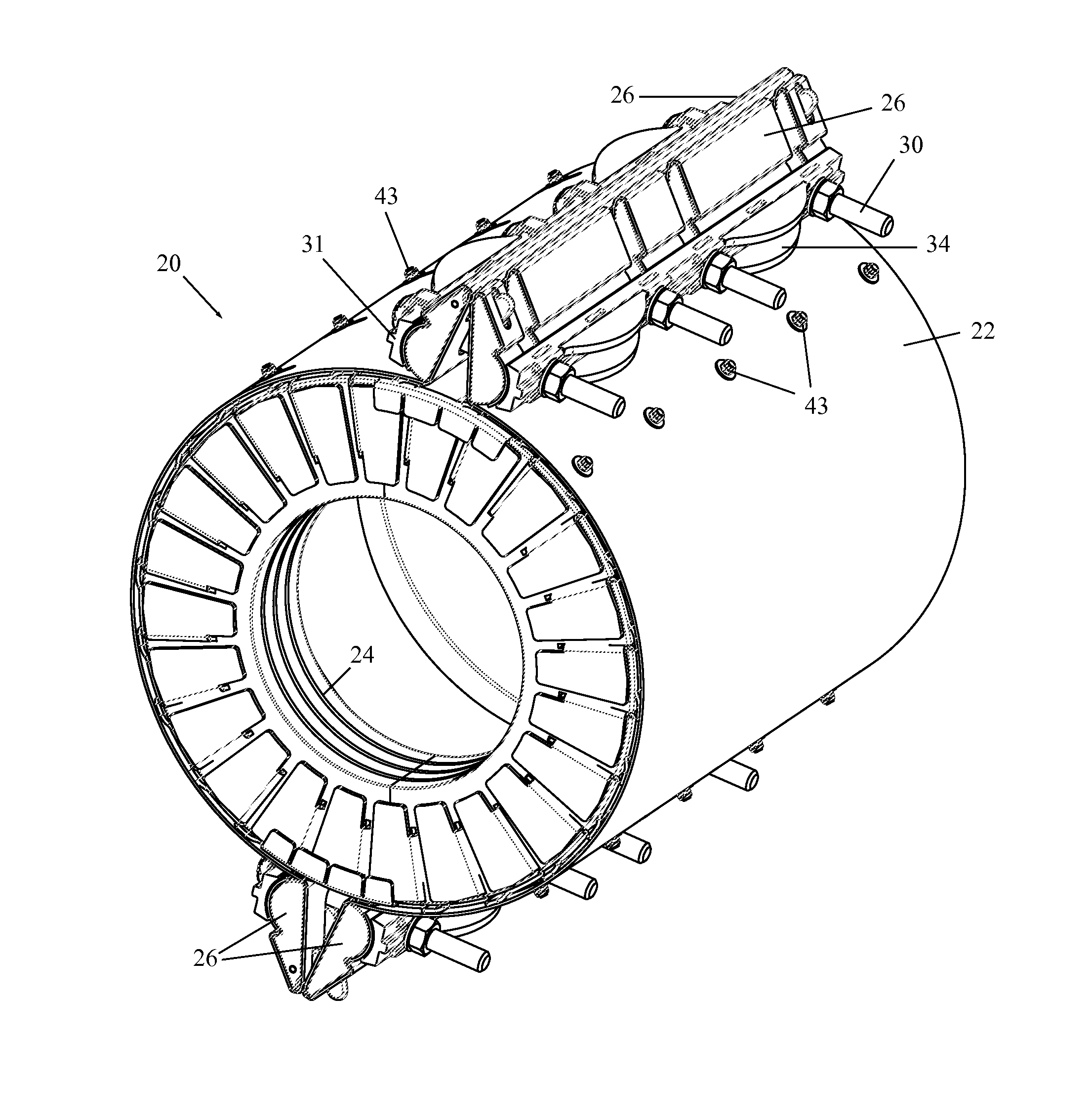
[0031]Reference is now made to FIGS. 6 and 7, which illustrate a pipe coupling capsulation assembly 20, constructed and operative in accordance with a non-limiting embodiment of the present invention.

[0032]Assembly 20 includes a band 22 having an inner annular seal element 24 wrappable around a pipe (not shown). Band 22 is typically, but not necessarily, made of metal and annular seal element 24 is typically, but not necessarily, made of an elastomer, such as natural or synthetic rubber. Annular seal element 24 is similar to the abovementioned prior art seal 5 but with important structural differences as will be explained below.

[0033]Opposing clamp members 26 extend radially outwards from ends of band 22 and are formed with mounting apertures 28. Clamp member 26 are clamped and tightened together with one or more tightening elements 30, such as but not limited to, bolts that pass through a bolt plate 31, and which are tightened by nuts 32 (with optional washers 33) at a nut plate 34...


PUM


Abstract

A pipe coupling capsulation assembly includes a band having an inner annular seal element wrappable around a pipe, opposing clamp members that extend from the band, and one or more tightening elements for clamping together the clamp members. Retaining elements are assembled to the annular seal element.

Description

FIELD OF THE INVENTION[0001]The present invention relates generally to pipe coupling assemblies, such as those used to sealingly connect pipes together or to repair breaks or leaks in pipes, and particularly for pipe coupling capsulation applications in which the pipe coupling fits over existing bell-shaped joints and sleeve joints and seals the joint.BACKGROUND OF THE INVENTION[0002]Many kinds of removable band-type couplings for pipes exist in the art. It is noted that throughout the specification and claims, the term “pipe” encompasses any kind of generally cylindrical object, and the terms “clamp” and “coupling” are used interchangeably.[0003]Pipeline leakage must be prevented for both economic and environmental reasons, depending on the nature of the fluid being transported. When needed repairs are inevitably carried out under field conditions, and in many situations there is a requirement that the flow of fluid in the pipeline may not be interrupted for any reason. Thus replac...

Claims


Application Information

Patent Timeline
IPC IPC(8): F16L21/06F16L21/03F16L21/00
CPCF16L21/065F16L21/03F16L21/002F16L21/005F16L55/1725F16L55/178
Inventor CHIPROOT, AVI
Owner KRAUSZ IND
Why Eureka
Try Eureka