Hose free sensor system for refrigerant unit

a technology for refrigerant units and sensors, applied in refrigeration machines, lighting and heating apparatus, refrigeration safety arrangements, etc., can solve problems such as reducing system performance, limiting the use of analog gauge sets, and significant deficiencies in conventional hose gauge systems

Active Publication Date: 2016-07-21
PARKER INTANGIBLES LLC
View PDF23 Cites 4 Cited by
  • Summary
  • Abstract
  • Description
  • Claims
  • Application Information

AI Technical Summary

Benefits of technology

[0009]The sensors may include high side and low side pressure and temperature, which permit installation into the refrigeration unit without hoses to collect system parameters, such as temperature and pressure. The system parameter measurements are transmitted from the sensors to a mobile portable electronic device via a wireless

Problems solved by technology

The conventional hose gauge system has significant deficiencies.
The disadvantage of using this form of coupling is that the analog gauge set can only be used for one type of system, i.e., the system refrigerant must be the same type as the trapped refrigerant inside of the hoses or refrigerant and oil contamination will occur.
Cross contamination can cause damage to the gauge set hoses and also

Method used


Image

  • Hose free sensor system for refrigerant unit
  • Hose free sensor system for refrigerant unit
  • Hose free sensor system for refrigerant unit

Examples


Embodiment Construction

[0031]Embodiments of the present invention will now be described with reference to the drawings, wherein like reference numerals are used to refer to like elements throughout. It will be understood that the figures are not necessarily to scale.

[0032]As referenced above, as used herein the term “refrigerant unit” or “refrigeration unit” is employed as a generalized term that encompasses equipment broadly used in heating, ventilation, air conditioning and refrigeration (HVACR) systems. Accordingly, it is understood that the present invention is not limited to usage in any particular type of device, and the term refrigerant unit or refrigeration unit is a generic term that encompasses all HVACR related and like devices in which the present invention may be employed.

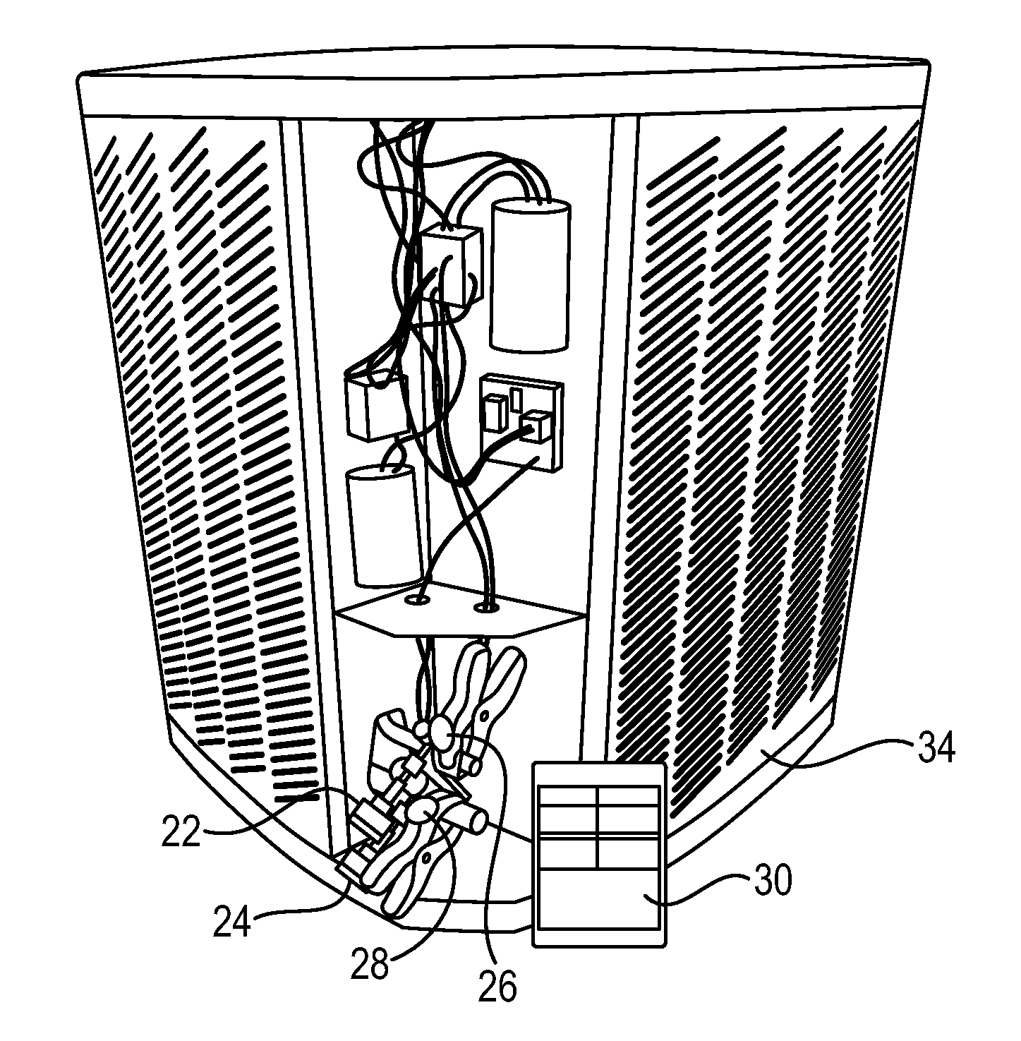
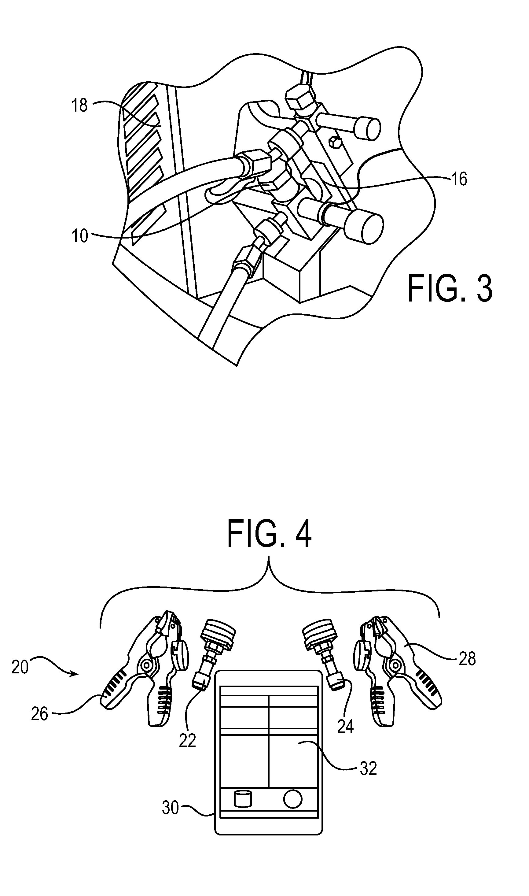
[0033]FIG. 4 depicts an exemplary hoseless sensor system 20 for use in sensing parameters and determining system conditions in a refrigerant unit. In exemplary embodiments, the sensor system includes a plurality of hoseless ...


PUM


Abstract

A hoseless sensor system for a refrigerant unit includes a plurality of hoseless sensors for sensing system parameters of the refrigerant unit, and a portable electronic device configured to receive the system parameters from the hoseless sensors and to calculate system conditions for the refrigerant based on the system parameters. The plurality of hoseless sensors includes a hoseless first pressure sensor and a hoseless second pressure sensor, and a hoseless first temperature sensor and a hoseless second temperature sensor. The temperature sensors are temperature sensor clamps. Each temperature sensor clamp includes a clamping portion configured to clamp on a tube of the refrigerant unit, the clamping portion including a sensor element to measure temperature about the tube. The clamping portion further includes a plurality of clamping teeth, and adjacent clamping teeth interlock in an overlapping configuration when the clamp closes inward beyond a threshold point.

Description

FIELD OF THE INVENTION[0001]The present invention is directed to enhanced sensor systems for refrigeration units for monitoring and collecting system conditions, such as superheat and subcooling.BACKGROUND OF THE INVENTION[0002]As used herein, the term “refrigerant unit” or “refrigeration unit” is employed as a generalized term that encompasses equipment broadly used in heating, ventilation, air conditioning and refrigeration (HVACR) systems. The HVACR markets have been served by manual, analog gauge sets for many decades. FIG. 1 depicts a conventional gauge set used for monitoring and collecting system conditions of a refrigerant unit such as pressure, which may then be used to calculate system parameters such as superheat and subcooling. The gauge set permits a service technician to see inside the system to help diagnose and repair faulty systems and components.[0003]As seen in FIG. 1, a conventional gauge set 10 is an analog gauge set that uses a set of hoses 11 connected to a ma...

Claims


Application Information

Patent Timeline
IPC IPC(8): F25B49/00
CPCF25B49/00F25B2700/19F25B2700/21
Inventor PARKER, CHRISTIAN D.PLASSMEYER, TIMOTHY A.RUETHER, JAMES D.DUNN, JASON T.ELLIS, SHAWN D.
Owner PARKER INTANGIBLES LLC
Why Eureka
Try Eureka