
Robot hand controlling method and robotics device

a robotics and hand technology, applied in the field of robotics hand control and robotics device, can solve the problems of increasing the cost of force sensors, reducing the cost of robot hands, and difficult downsizing of robot hands, and achieves simple configuration, and accurate adjustment of grip force

Active Publication Date: 2016-08-04
CANON KK
View PDF50 Cites 16 Cited by
  • Summary
  • Abstract
  • Description
  • Claims
  • Application Information

AI Technical Summary

Benefits of technology

The technical effect of this patent is that it provides a way for robots to have precise control over their grip strength through a simplified mechanism. This allows them to better hold objects without causing damage or difficulty during manipulation tasks.

Problems solved by technology

The technical problem addressed in this patent is the difficulty in accurately controlling the grip force of a robot hand when the robot hand is gripping a workpiece, due to the physical properties of the workpiece and the friction generated in the driving mechanism of the robot hand. Existing methods such as using a disturbance estimation observer or an external force sensor have limitations such as difficulty in identifying compensation coefficients and hysteresis, and the need for separate components that increase the cost and decrease the accuracy of the control.

Method used


Image

  • Robot hand controlling method and robotics device
  • Robot hand controlling method and robotics device
  • Robot hand controlling method and robotics device

Examples


Embodiment Construction

[0021]Preferred embodiments of the present invention will now be described in detail in accordance with the accompanying drawings.

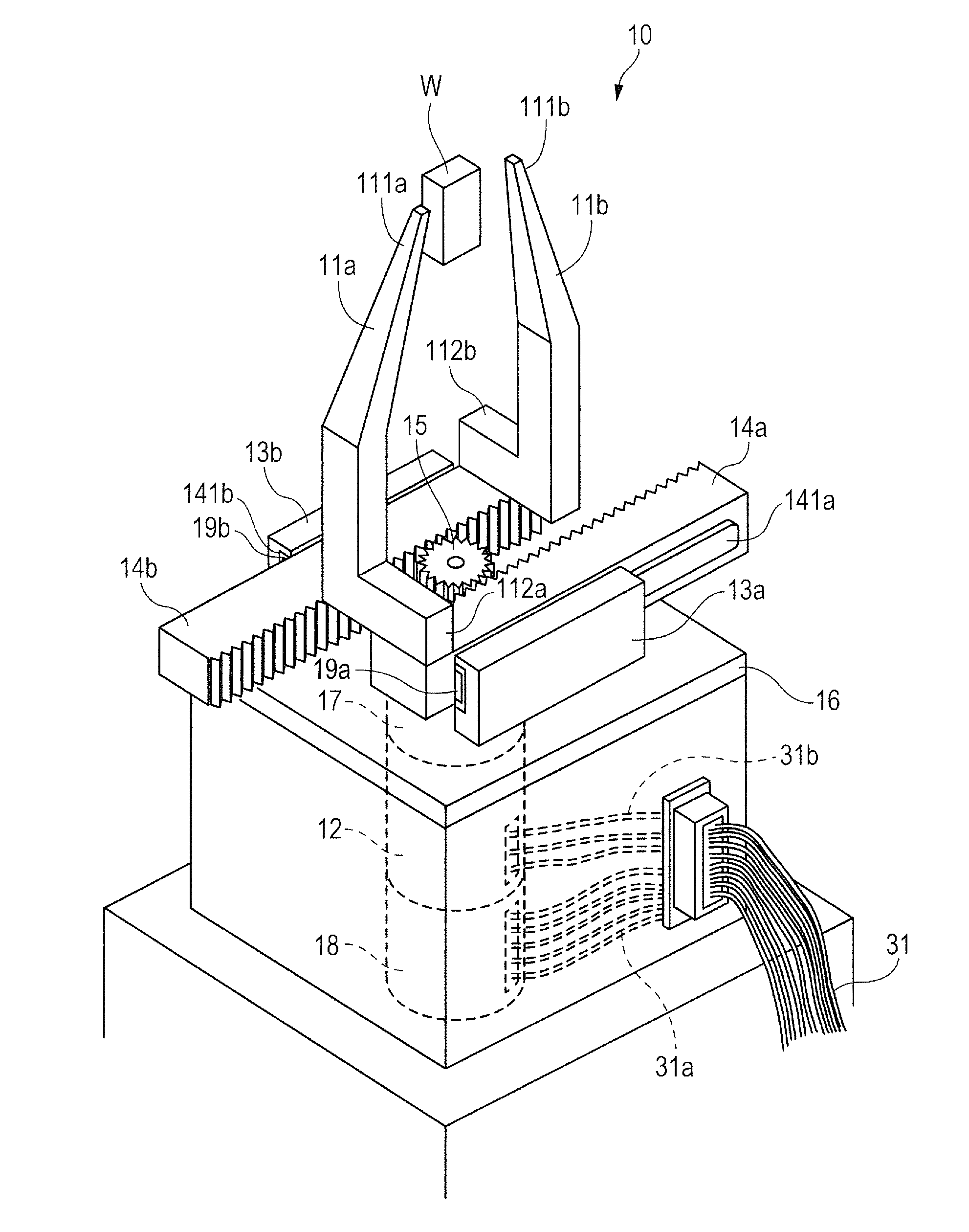
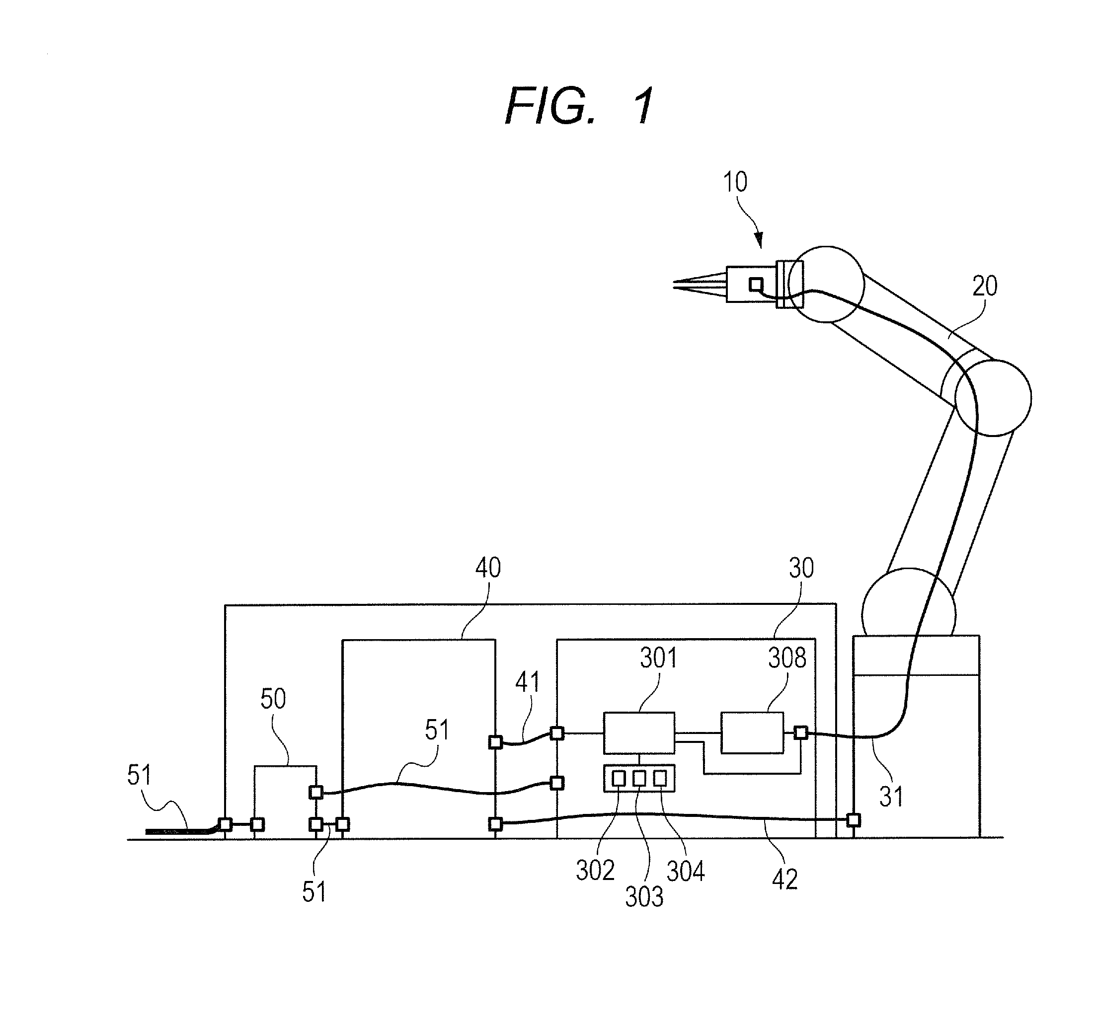
[0022]An embodiment of the present invention will now be described with reference to FIGS. 1 to 7. FIG. 1 is a schematic diagram illustrating a schematic configuration of a robotics device according to the embodiment of the present invention.

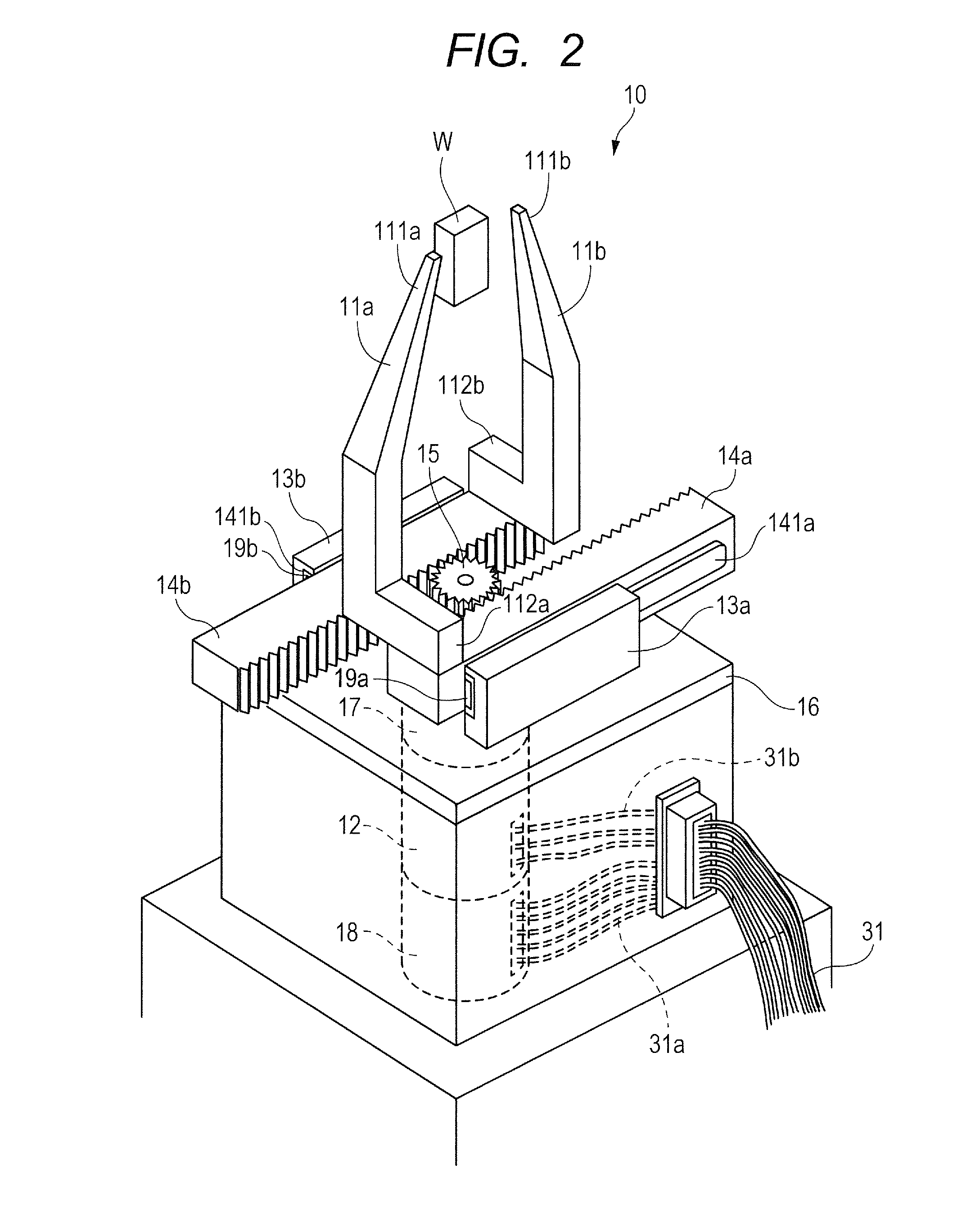
[0023]A robotics device 1 includes: a robot hand 10 capable of grasping a work W (see FIG. 2); and a robot arm 20 including the robot hand 10 at a tip, the robot arm 20 controlling the position of the robot hand 10 and including a plurality of joints. The robotics device 1 further includes: a hand controlling unit 30 as a controlling unit that controls the robot hand 10; and a controlling instruction unit 40 capable of transmitting various controlling instructions. The robotics device 1 further includes a power controlling unit 50 that supplies power to the elements included in the robotics device 1 through power supp...


PUM


Abstract

A robot hand controlling method executes calculating a position and changing grip force when the grip force for gripping a work W is to be changed in a state that fingers are gripping the work W with first grip force. In the calculating the position, the hand controlling unit uses a correlation value indicating a relationship between the grip force of the fingers and position of fixing portions, the first grip force, and second grip force that is a target value of the grip force to calculate the position of the fixing portions in gripping the work W with the second grip force. In the changing the grip force, the hand controlling unit drives a motor by calculating a driving quantity of the motor necessary for moving the fingers to the calculated position of the fixing portions.

Description


Claims


Application Information

Patent Timeline
Owner CANON KK
Learn More