Portable lighting devices with multiuse lanyards and detachable lanyards

a technology of multi-use lanyards and portable lighting, which is applied in the direction of lighting support devices, electric lighting with batteries, lighting and heating apparatus, etc., can solve the problems of inconvenient attachment for a variety of situations, inability to attach the method, and inability to meet the needs of users, and achieve the effect of convenient functionality

Active Publication Date: 2016-08-04
INDAL REVOLUTION
View PDF18 Cites 8 Cited by
  • Summary
  • Abstract
  • Description
  • Claims
  • Application Information

AI Technical Summary

Benefits of technology

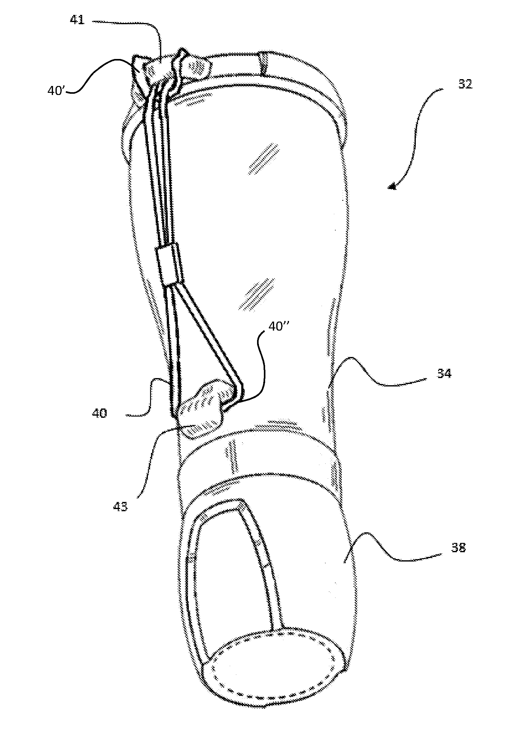
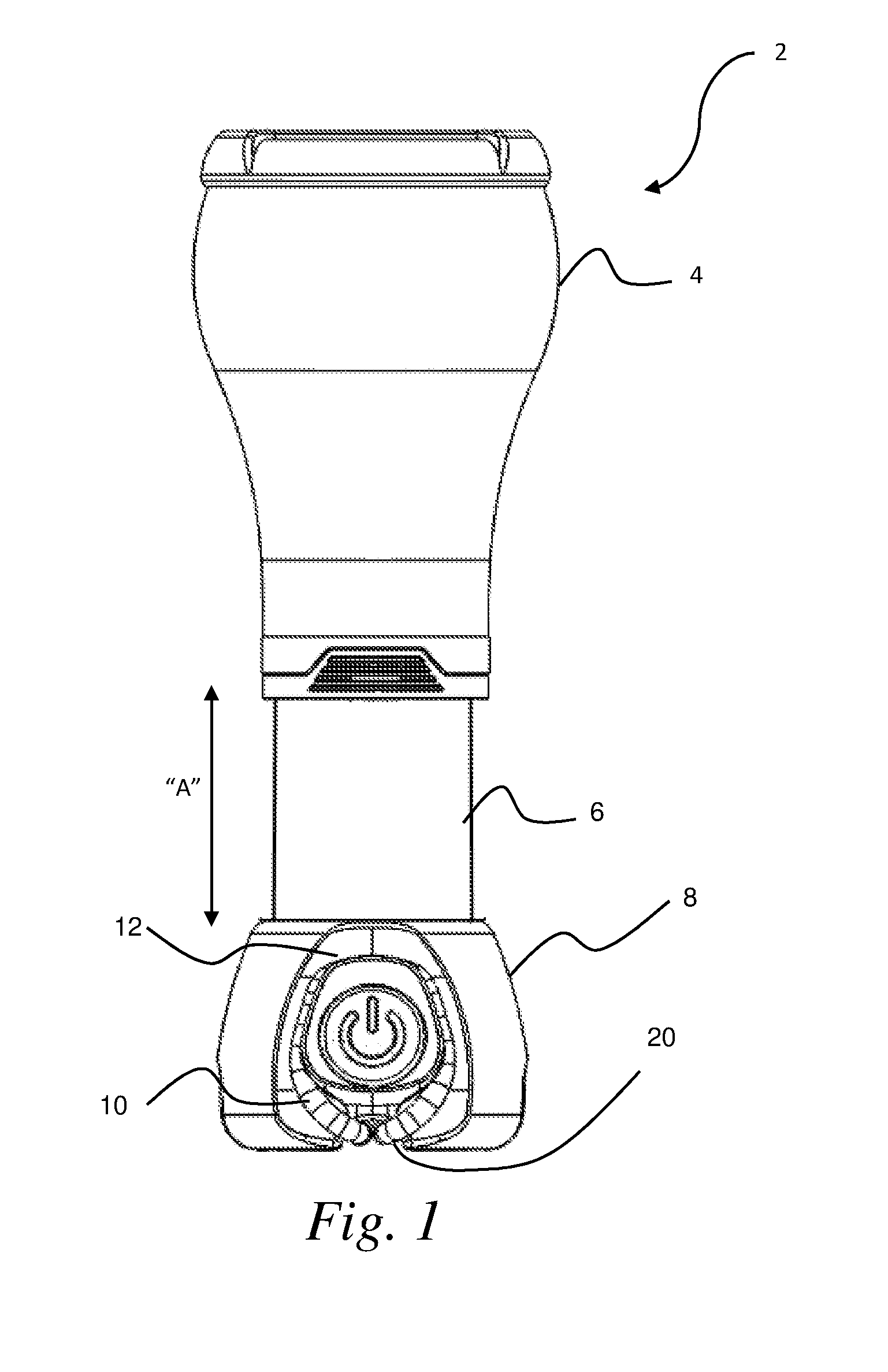
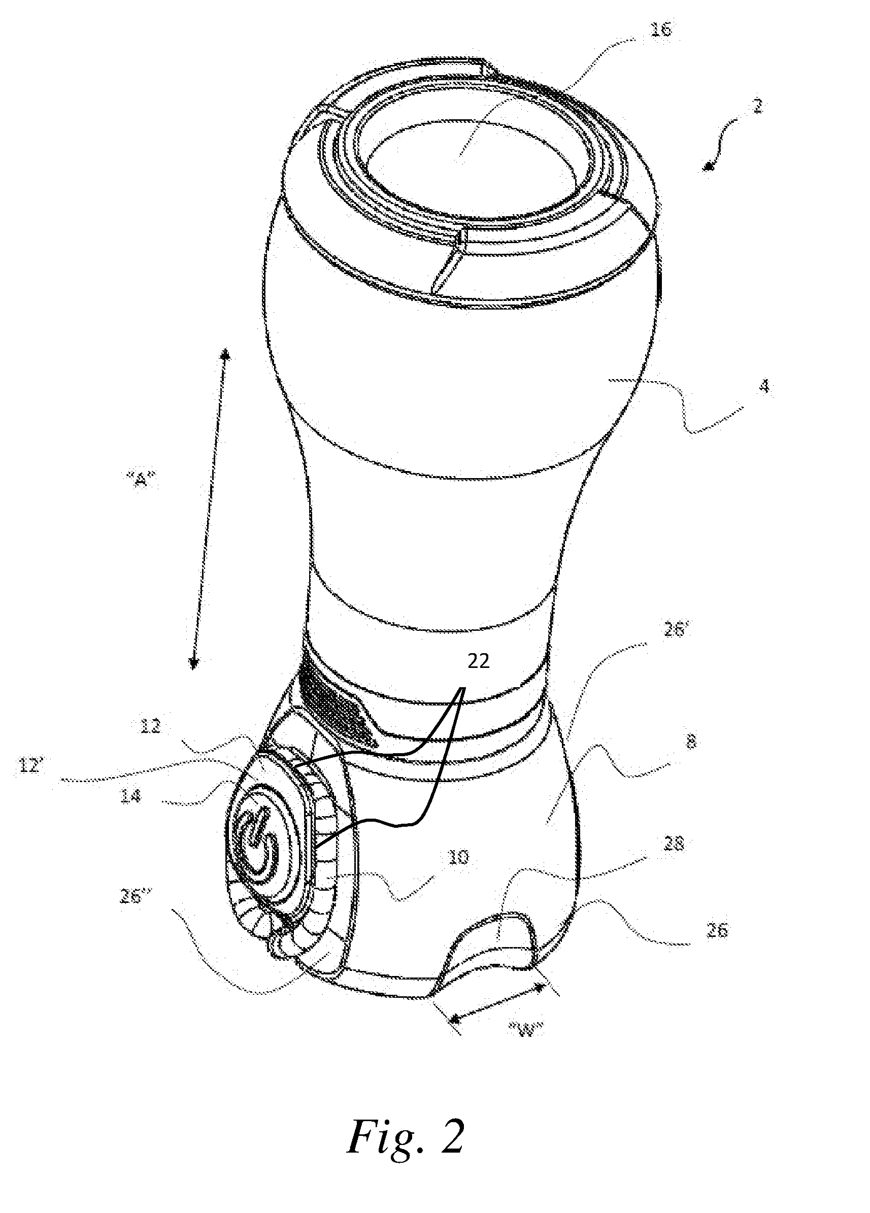
[0006]In some embodiments of the present disclosure, a portable lighting device comprises a light source; a body having a base and a lens or globe; a flexible and / or elastic lanyard anchored to the body of the portable lighting device; and a channel formed on the body, the channel being configured to receive and retain a portion of a free closed loop of the elastic lanyard, with the elastic lanyard being stretched under tension. The elastic lanyard can be fixedly anchored to the base, and the base can have one or more notches disposed on a bottommost surface thereof, wherein the one or more notches and lanyard are configured such that a portion of the lanyard can be stretched from the based and upward onto the body to be attached to the channel, while clearing the bottommost wall of the base by being recessed into the one or more notches, so as to avoid interference with the base resting on a surface (e.g., during storage of the lanyard on the lighting device). On the other hand, the fixed anchor point of the lanyard on the base can provide convenient functionality for use in attaching the base to an object, by stretching the free closed loop of the elastic lanyard around an object, and then attaching it to the channel to secure the base to the object, with or without, a conveniently accessible termination point of the object / surface being available.
[0010]In some embodiments, a bottommost surface of the base extends below the bottom surface section to which the detachable member can be magnetically attached. As such, in some embodiments, when the detachable member is attached to the bottom surface section, it can clear a surface upon which the base can rest (this can avoid contact of the detachable member against a resting surface when it is attached to the base, to avoid inadvertent displacement of the detachable member). Moreover, the detachable member can be easily attached to, or hung from, an object by the lanyard fixedly attached to the detachable member. The detachable member can be typically smaller than the body of the lighting device (1 / 4th-1 / 20th, or less, the volume of the body of the lighting device) and can be easily manipulated for tying or connecting the detachable member to the object / surface, and then the body portion of the portable lighting device can be conveniently and selectively attached or detached from the detachable member to retain the portable lighting device to the object.

Problems solved by technology

However, such attachments are not convenient for a variety of situations.
For example, if a termination / end point of the object / surface is not easily accessible (e.g., a long tree branch), in order to hang the lighting device using the anchored closed loop lanyard, the user would need to either tie the lanyard, or loop the lanyard though itself, both of which methods of attachment can be impossible or impractical, given that the lanyard is anchored to the lighting device.
Moreover, even if the lanyard and lighting device are attached by tying to the object / surface, it is frequently inconvenient if the lighting device needs to be removed and reattached frequently to the object / surface.

Method used


Image

  • Portable lighting devices with multiuse lanyards and detachable lanyards
  • Portable lighting devices with multiuse lanyards and detachable lanyards
  • Portable lighting devices with multiuse lanyards and detachable lanyards

Examples


Embodiment Construction

[0022]In the present description, where used, the terms “about,” or “approximately” mean±20% of the indicated range, value, or structure, unless otherwise indicated. It should be understood that the terms “a” and “an” as used herein refer to “one or more” of the enumerated components. The use of the alternative (e.g., “or”) should be understood to mean either one, both, or any combination thereof of the alternatives, unless expressly stated otherwise. As used herein, the terms “include” and “comprise” are used synonymously, and those terms and variants thereof are intended to be construed in a non-limiting, open sense.

[0023]In the present description, certain specific details are set forth in order to provide a thorough understanding of various embodiments of the present disclosure. However, upon reviewing this disclosure, one skilled in the art will understand that the invention may be practiced without many of these details. In other instances, well-known or widely available struc...


PUM


Abstract

Apparatus and methods for attaching portable lighting devices to objects / surface are provided. In some embodiments, an elastic lanyard is anchored to a body portion of a portable lighting device and a free closed loop portion can be looped around an object, and / or a channel formed on the body portion. In some embodiments, the channel is formed on a base of the body portion and the elastic lanyard can be stretched about an object disposed between a bottom surface of the base and the lanyard. In other embodiments, a lanyard is anchored to a detachable member that is magnetically attachable to a body portion of the portable lighting device.

Description

CROSS REFERENCE TO RELATED APPLICATION(S)[0001]This application claims the benefit of U.S. Provisional Patent Application No. 62 / 099,637, filed Jan. 5, 2015, which is incorporated herein by reference in its entirety.BACKGROUND[0002]1. Technical Field[0003]The present disclosure relates to portable lighting devices, and in particular, to lanterns, flashlights, and combination flashlight / lanterns having flexible and / or elastic multiuse lanyards.[0004]2. Description of Related Art[0005]Closed loop attachment lanyards are commonly provided as anchored attachment members on portable lighting devices (e.g., lanterns and flashlights) since they provide a convenient manner in which to attach the lighting device to an object / surface when a termination end of the object / surface is easily accessible (e.g., looping a lanyard over a user's wrist). However, such attachments are not convenient for a variety of situations. For example, if a termination / end point of the object / surface is not easily ...

Claims


Application Information

Patent Timeline
Patent Type & Authority Applications(United States)
IPC IPC(8): F21V21/08F21V21/14
CPCF21V21/145F21V21/0816F21L4/005F21V21/0965
Inventor PONTANO, PETERQUINN, COLINESAREY, GRAEMEODELL, JAMI
Owner INDAL REVOLUTION
Why Eureka
Try Eureka