Power socket

a power socket and socket technology, applied in the direction of coupling device connection, two-part coupling device, electrical apparatus, etc., can solve the problems of led burning out, specific structure disclosure, and prior art disclosure of how to dispose of light sensors into power sockets, etc., to facilitate the disclosure of the present disclosure

Inactive Publication Date: 2016-08-04
POWERTECH INDAL
View PDF7 Cites 2 Cited by
  • Summary
  • Abstract
  • Description
  • Claims
  • Application Information

AI Technical Summary

Benefits of technology

[0011]In summary, exemplary embodiments of the present disclosure provide a technique for controlling at least one power socket through wireless remote control. Each of the power sockets is disposed with at least one photo-interrupter to sense whether a plug is inserted into the jack set of the power socket. Therefore, a monitor can determine the operation state of each jack set of each power socket according to the sensing results of the photo-interrupters in the power sockets, and a user can cut off or maintain power supplied from the jack set through wireless remote control so as to provide or stop providing power to an electronic device which is connected to the jack set.
[0012]In order to further the understanding regarding the present disclosure, the following embodiments are provided along with illustrations to facilitate the disclosure of the present disclosure.

Problems solved by technology

But the prior art does not disclose how to dispose the light sensor into the power socket, and only simply discloses or shows the coupled relationship of the elements in the power socket.
However, U.S. Pat. No. 7,575,467 fails to specifically disclose the structure of the sensor.
Too little light means that either the LED is burned out or a larger or adequately shaped foreign object has been inserted.
Therefore, if there is too little or too much light, the plug component sensor would indicate an unacceptable condition.
As such, the detecting means disclosed by U.S. Pat. No. 6,176,718 is not adapted to detect the blade without the aperture.
Moreover, no insulation or insulating housing is disposed between the sensor and the inserted blade, so it may cause a short circuit phenomenon between the inserted blade and the sensor, an incorrect sensing result generated by the sensor, or even damage of the sensor and the power socket, which may affect the safety of the power socket.
When many power sockets have been inserted with plugs of a plurality of electronic devices, a user may be unable to clearly know which power sockets have been inserted with a plug.
Consequently, the user will be unable to effectively manage the power sockets.

Method used


Image

  • Power socket
  • Power socket
  • Power socket

Examples


Embodiment Construction

[0022]The aforementioned illustrations and following detailed descriptions are exemplary for the purpose of further explaining the scope of the present disclosure. Other objectives and advantages related to the present disclosure will be illustrated in the subsequent descriptions and appended drawings.

[0023]It should be understood that the usage of “first”, “second” and “third” intends to distinguish one element from another, and the element should not be limited by the term. Therefore, hereinafter a first element is interchangeable with a second element. The term “and / or” includes one and one or more of the combination in the group as described.

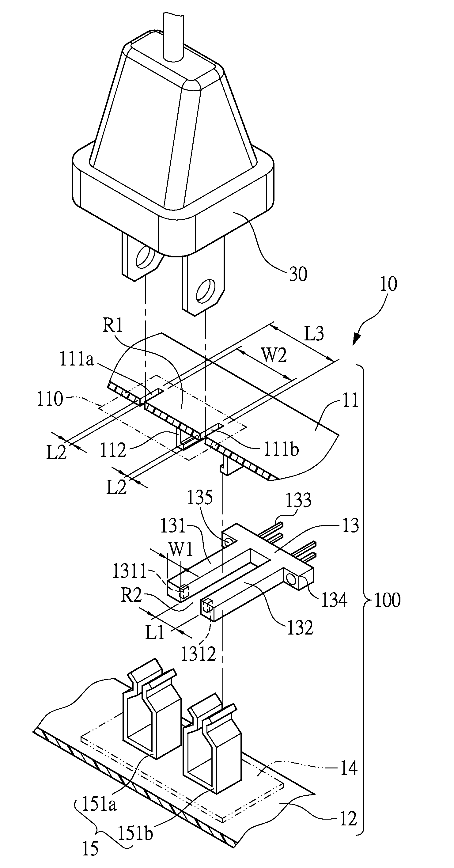
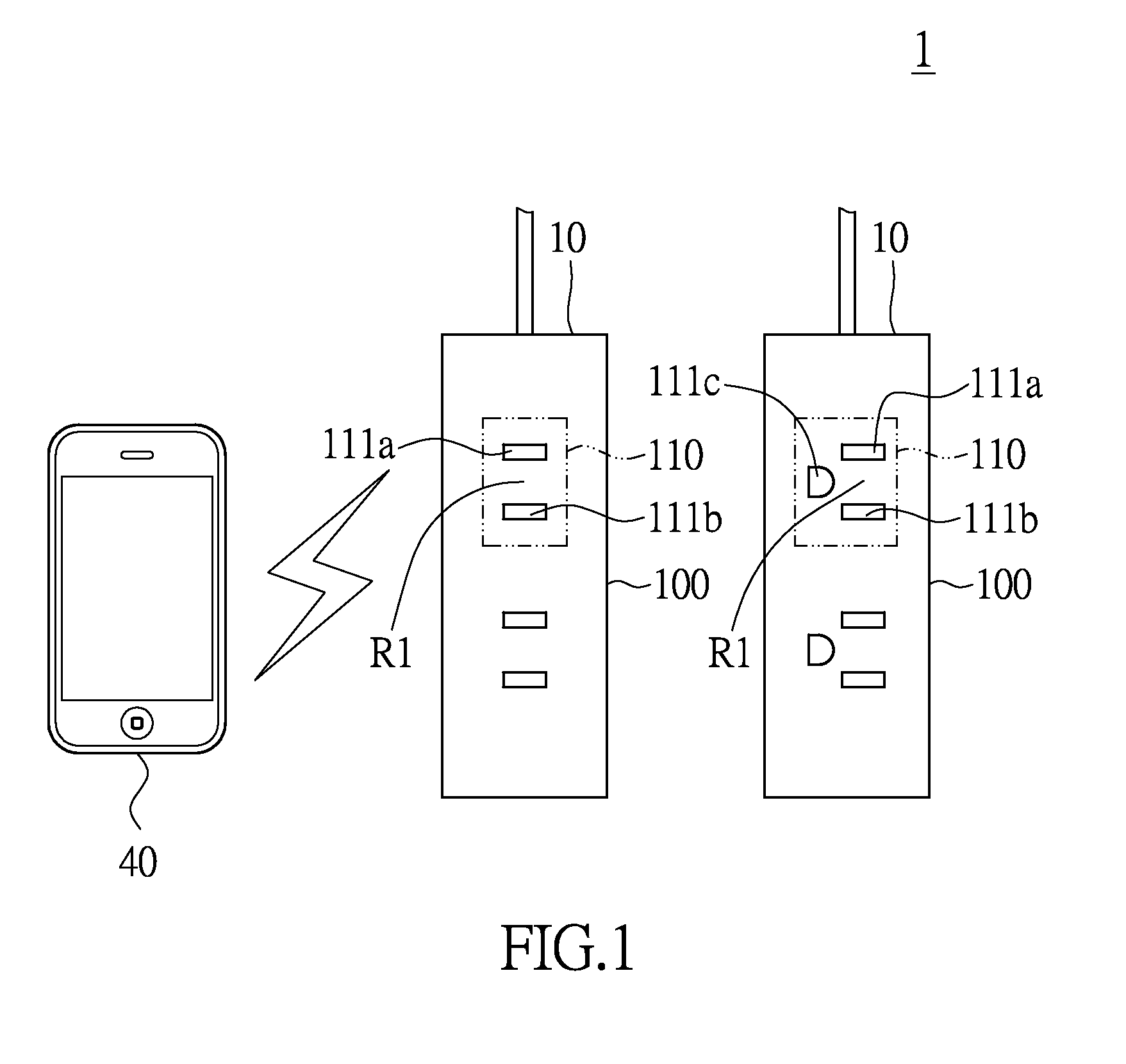
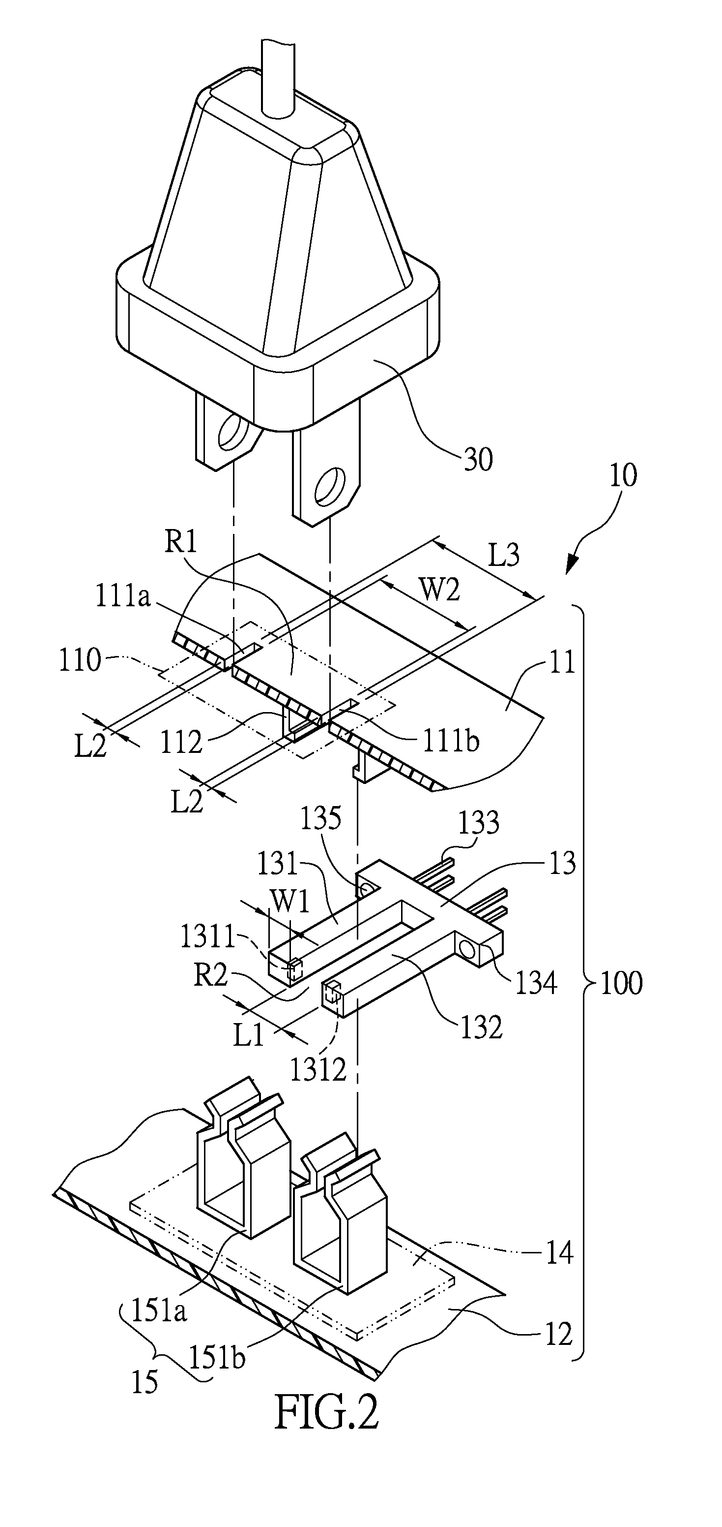
[0024]Please refer to FIG. 1, which shows an architecture diagram of a power socket system provided in accordance to an embodiment of the present disclosure. The power socket system 1 includes at least one power socket 10 and a monitor 40. The exact number of power sockets 10 may be configured depending upon the practical operation needs, an...


PUM


Abstract

A power socket includes a main body and a photo-interrupter. The main body has a jack set, and the jack set has a first jack and a second jack. A partition region is formed between the first jack and the second jack. The photo-interrupter is disposed in the body and under the jack set. The photo-interrupter has a first sensing portion and a second sensing portion. The first sensing portion is under the partition region, and the width of the first sensing portion is less than the width of the partition region. A sensing region is formed between the first sensing portion and the second sensing portion. The sensing region is under the first jack, and the length of the sensing region is more than or equal to the width of the first jack.

Description

BACKGROUND OF THE INVENTION[0001]1. Field of the Invention[0002]The present disclosure relates to a power socket; in particular, to a power socket with a photo-interrupter for sensing presence of a plug inserted in the power socket.[0003]2. Description of Related Art[0004]In recent years, more and more power sockets are disposed with a light sensor for sensing whether the plug is inserted into the jack set of the power socket. For example, CN Patent Pub. No CN103500902A, CN203631896 U, CN101859964 A, or CN102035521 B, disclose a power socket with a light sensor for sensing whether a plug is inserted into the jack set of the power socket. More specifically, when the plug is inserted into the jack set of the power socket, a light emitted from a light-emitting portion of the light sensor is interrupted by the plug. Correspondingly, the light-receiving portion of the light sensor does not receive the light emitted from the light-emitting portion, and then the power socket determines whe...

Claims


Application Information

Patent Timeline
Patent Type & Authority Applications(United States)
IPC IPC(8): H01R13/703H01R24/76H01R13/629H01R13/717H01R13/66
CPCH01R13/7038H01R13/717H01R13/6683H01R2103/00H01R13/629H01R24/76H01R13/6691H04N1/00885
Inventor HSU, JUNG-HUI
Owner POWERTECH INDAL
Why Eureka
Try Eureka